


Collegamento di un trasformazione trifaser è essenziale per una distribuzione di energia sicura e affidabile nei sistemi industriali, commerciali e di energia rinnovabile. Questa guida copre tutti gli aspetti, dai concetti fondamentali agli approfondimenti di mercato, dai dettagli tecnici ai consigli per la scelta, strutturati in modo da garantire chiarezza, efficacia SEO e maggiore EEAT.
1. Spiegazione del concetto centrale
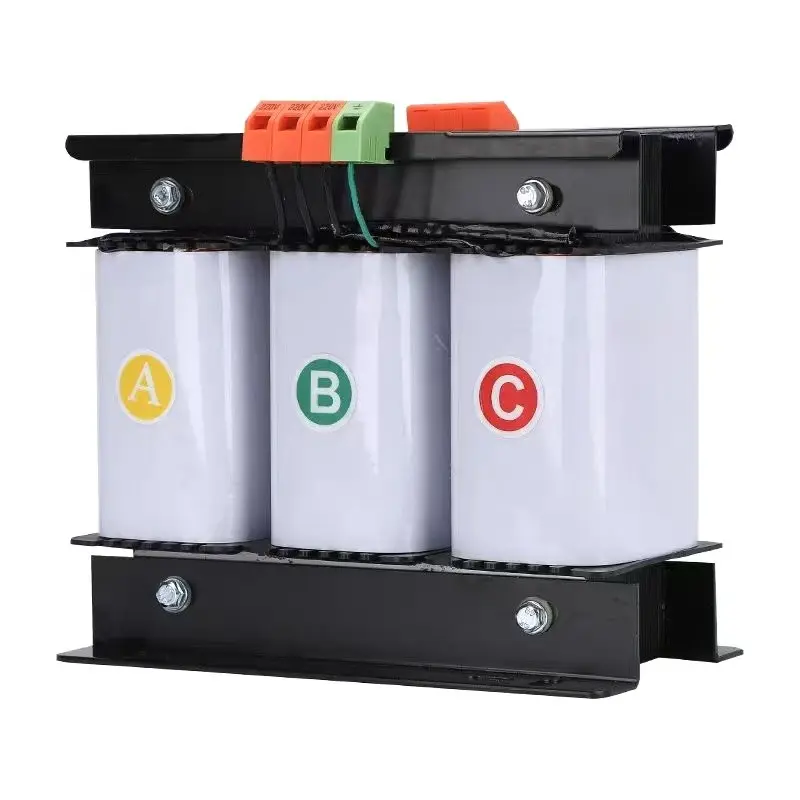
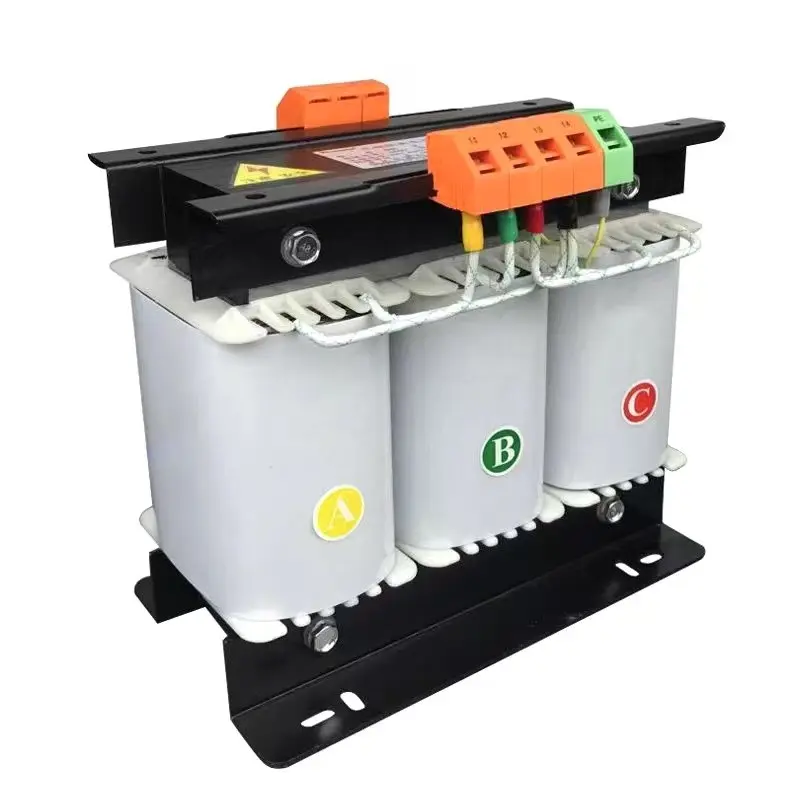
A trasformatore trifase è un dispositivo che trasferisce energia elettrica tra tre circuiti a corrente alternata (CA). A differenza di trasformatori monofaseIl sistema utilizza tre gruppi di avvolgimenti, ognuno dei quali sfasato di 120°, per gestire in modo più efficiente i carichi bilanciati o sbilanciati. I sistemi trifase sono onnipresenti nelle utenze e nelle industrie pesanti grazie a:
- Maggiore densità di potenza: Fornisce più potenza per conduttore.
- Materiale conduttore ridotto: Tre fili invece di quattro per una potenza monofase equivalente.
- Coppia fluida per i motori: Ideale per applicazioni pesanti.
Esistono due configurazioni di avvolgimento primario:
- Delta (Δ) Connessione: Avvolgimenti collegati in un anello triangolare; non è necessario il neutro.
- Connessione Wye/Star (Y): Un'estremità di ciascun avvolgimento si unisce a un punto neutro, consentendo carichi da linea a neutro.

2. Aree di applicazione
I trasformatori trifase servono un'ampia gamma di settori:
- Strutture industriali: Alimentazione di macchine CNC, pompe, compressori e controlli di processo.
- Centri dati: Garantire un'alimentazione ininterrotta e bilanciata per i server critici.
- Impianti di energia rinnovabile: Aumentare le tensioni delle turbine eoliche o degli impianti solari per l'integrazione nella rete.
- Edifici commerciali: Distribuire in modo efficiente l'energia di HVAC, ascensori e grandi carichi.
- Servizi e sottostazioni: Reti di trasmissione e distribuzione ad alta tensione.
Molte applicazioni moderne integrano anche monitoraggio intelligente-temperatura, carico e armoniche in tempo reale per ottimizzare le prestazioni e prevedere le esigenze di manutenzione.
3. Tendenze del mercato e contesto di sviluppo
Il mercato globale dei trasformatori ha registrato una forte crescita, trainata dai programmi di elettrificazione, dall'integrazione delle energie rinnovabili e dalla modernizzazione delle infrastrutture. Secondo una recente analisi di settore, il mercato è stato valutato a 63,8 miliardi di dollari nel 2024 e si prevede che crescerà ad un tasso CAGR del 6,6% fino al 2034 Global Market Insights Inc.. I fattori chiave includono:
- Aumento della spesa T&D: Le economie in via di sviluppo stanno ampliando la portata della rete.
- Digitalizzazione: L'integrazione di smart-grid e IoT aumenta la domanda di unità avanzate.
- Regolamenti sull'efficienza energetica: Standard più severi stimolano l'adozione di nuclei a bassa perdita.
Riflettori puntati sulla regione: L'Asia-Pacifico è in testa con oltre 31% di fatturato globale nel 2024, grazie all'elettrificazione rurale su larga scala e ai progetti rinnovabili. GlobeNewswire.
4. Parametri tecnici e fasi di installazione
4.1 Caratteristiche tecniche principali
| Parametro | Gamma tipica |
|---|---|
| Potenza nominale (kVA) | Da 50 kVA a 10.000 kVA (o superiore) |
| Rapporti di tensione | ad esempio, 11 kV/415 V, 33 kV/11 kV |
| Configurazioni di avvolgimento | Δ/Δ, Y/Y, Δ/Y, Y/Δ |
| Metodo di raffreddamento | ONAN, ONAF, OFAF, ecc. |
| Impedenza (%) | 4 - 8 % (influenza le correnti di guasto) |
4.2 Guida all'aggancio passo-passo
- La sicurezza prima di tutto:
- Disalimentare la rete a monte; verificare l'assenza di tensione.
- Secondario di terra se richiesto dalla normativa locale.
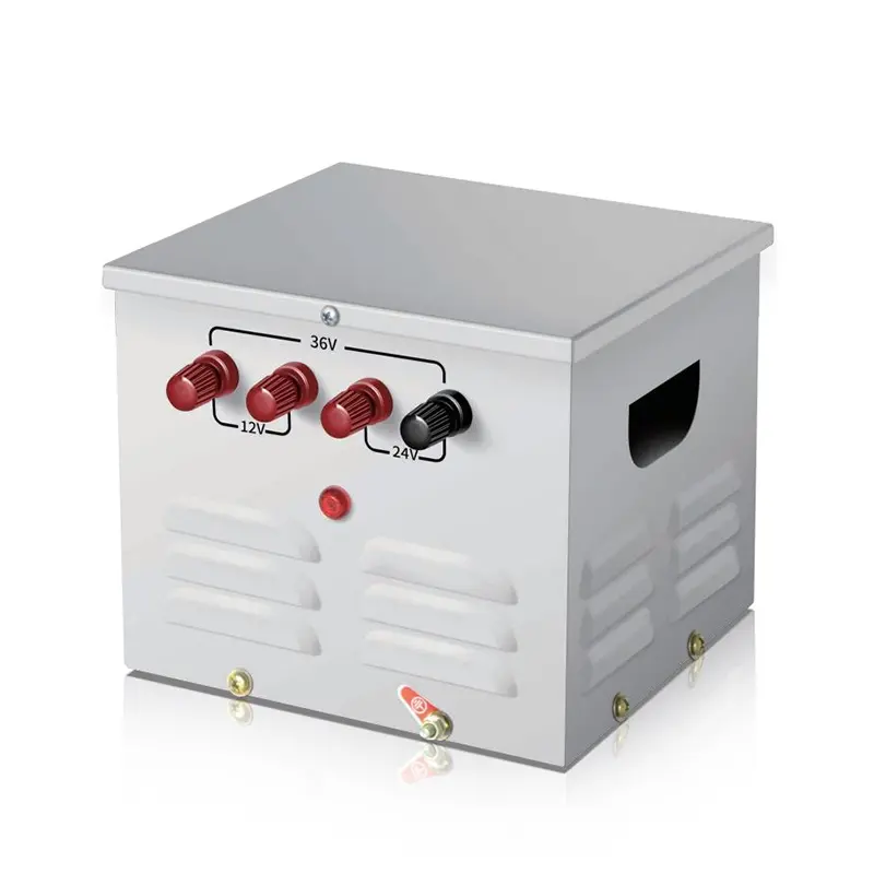
- Identificare i terminali:
- Lato primario: L1, L2, L3 (e talvolta il neutro "N").
- Lato secondario: T1, T2, T3 (più "N" se si tratta di una derivazione).
- Selezionare il Gruppo di vettori:
- Assicura che lo spostamento di fase corrisponda al sistema (ad esempio, Yd11, Dy5).
- Controllare la targa dati o il diagramma fasoriale.
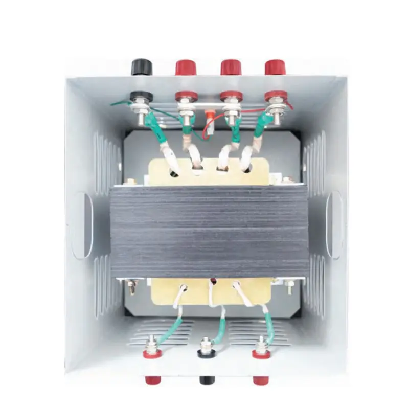
- Collegare gli avvolgimenti primari:
- Per delta, unire le estremità in un triangolo: U2→V1, V2→W1, W2→U1.
- Per segalelegare un'estremità di ciascuna bobina al neutro; collegare la rete alle altre estremità.
- Collegare gli avvolgimenti secondari:
- Rispecchiare la configurazione primaria o scegliere quella alternativa (ad esempio, Δ primaria → Y secondaria).
- Isolamento e messa a terra:
- Applicare boccole adeguate alla fase.
- Collegare il serbatoio e il punto neutro alla terra.
- Controlli di pre-energizzazione:
- Test di resistenza dell'isolamento (megger).
- Test di polarità per confermare la corretta sequenza delle fasi.
- Test di rapporto per verificare il rapporto di rotazione.
- Messa in servizio:
- Dare una leggera tensione; monitorare la corrente a vuoto e le temperature.
- Applicare gradualmente il carico; verificare l'equilibrio della tensione e l'assenza di vibrazioni.

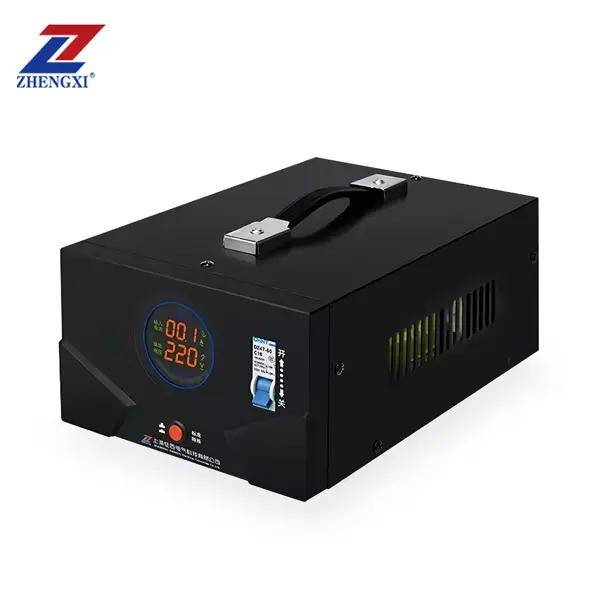
5. Confronto con stabilizzatori monofase e statici
| Caratteristica | Trasformatore trifase | Trasformatore monofase | Stabilizzatore statico |
|---|---|---|---|
| Capacità di alimentazione | Alto (kVA-MVA) | Da basso a medio | Da basso a medio |
| Efficienza | 98-99 % | 96-98 % | 95-97 % |
| Applicazione | Industriale, Grid | Residenziale, Comm. leggero | Regolazione della tensione |
| Gestione delle armoniche | Moderato | Limitato | Eccellente |
| Manutenzione | Richiede controlli dell'olio, ecc. | Simile | Minimo (stato solido) |
Gli stabilizzatori di tensione statici utilizzano convertitori elettronici di potenza per regolare rapidamente la tensione, ma mancano dell'isolamento e della capacità di alta potenza dei trasformatori tradizionali.
6. Consulenza per l'acquisto e guida alla selezione
Nella scelta di un trasformatore trifase, considerare:
- Capacità nominale e profilo di carico: Tenere conto dell'espansione futura (margine 15-25%).
- Compatibilità del gruppo vettoriale: Deve corrispondere alle apparecchiature a monte e a valle per evitare correnti circolanti.
- Certificazioni e standard: IEC 60076, IEEE C57.xx, ISO9001, CE, RoHS.
- Requisiti di raffreddamento: ONAN per gli ambienti standard, ONAF/OFWF per gli ambienti ad alto carico o difficili.
- Efficienza e perdite: I nuclei a bassa perdita (acciaio amorfo) riducono i costi operativi.
- Garanzia e assistenza: Cercate ≥ 2 anni di garanzia e reti di assistenza locali.
- Costo totale di gestione: Considerate l'installazione, la manutenzione e le perdite di energia.
Suggerimento: Coinvolgere i fornitori che offrono test di accettazione in fabbrica (FAT) e una documentazione dettagliata per garantire la conformità delle prestazioni.
7. DOMANDE FREQUENTI
D1: Posso mettere in parallelo due trasformatori trifase?
R: Sì, se hanno valori nominali, gruppi vettoriali e percentuali di impedenza identici per evitare correnti circolanti e problemi di condivisione del carico.
D2: Come si fa a scegliere tra le connessioni Δ/Δ e Y/Δ?
R: Utilizzare Δ/Δ per carichi industriali bilanciati senza neutro; Y/Δ quando è necessario un neutro per carichi da linea a neutro o per ridurre la tensione.
D3: Quali sono le fasi comuni di risoluzione dei problemi per le tensioni sbilanciate?
A:
- Verificare i collegamenti degli avvolgimenti e il gruppo di vettori.
- Verificare che non vi sia una cattiva sequenza di fasi o collegamenti allentati.
- Misurare le correnti di carico; bilanciare i carichi tra le fasi.
Trasformatori trifase sono la spina dorsale dei moderni sistemi di alimentazione. Comprendendo i principi fondamentali, seguendo procedure di installazione precise e scegliendo le specifiche giuste, si assicurano affidabilità ed efficienza a lungo termine. Che si tratti di una fabbrica, di un centro dati o di un impianto di energia rinnovabile, un collegamento corretto e decisioni di acquisto informate massimizzeranno i tempi di attività e ridurranno al minimo i costi di gestione.

Che cos'è un trasformatore di controllo? Una guida completa per le applicazioni industriali
Qual è la differenza tra un autotrasformatore e un trasformatore di isolamento?
Prezzo e guida all'acquisto dei trasformatori di isolamento
Trasformatore di isolamento toroidale monofase da 220v a 220v con 2 prese di uscita
Trasformatore di controllo step-down per illuminazione portatile monofase JMB 25Va~50Kva
Trasformatore di controllo trifase a secco ad alta efficienza da 500 VA a 1000 KVA 415 V 400 V 380 V