


Um transformador de isolamento proporciona uma separação galvânica entre os seus enrolamentos primário e secundário. Essa separação eléctrica melhora a segurança, reduz o ruído de modo comum e a interferência do circuito de terra e protege o equipamento sensível. Antes da instalação, teste ou aquisição, é importante ser capaz de confirmar que uma unidade é um verdadeiro transformador de isolamento - e não um autotransformador ou um transformador de controlo diferente. Este guia apresenta passos testados no terreno, que dão prioridade à segurança, e a documentação que deve ser exigida aos fornecedores.
1. Verificar primeiro a placa de identificação e a ficha de dados
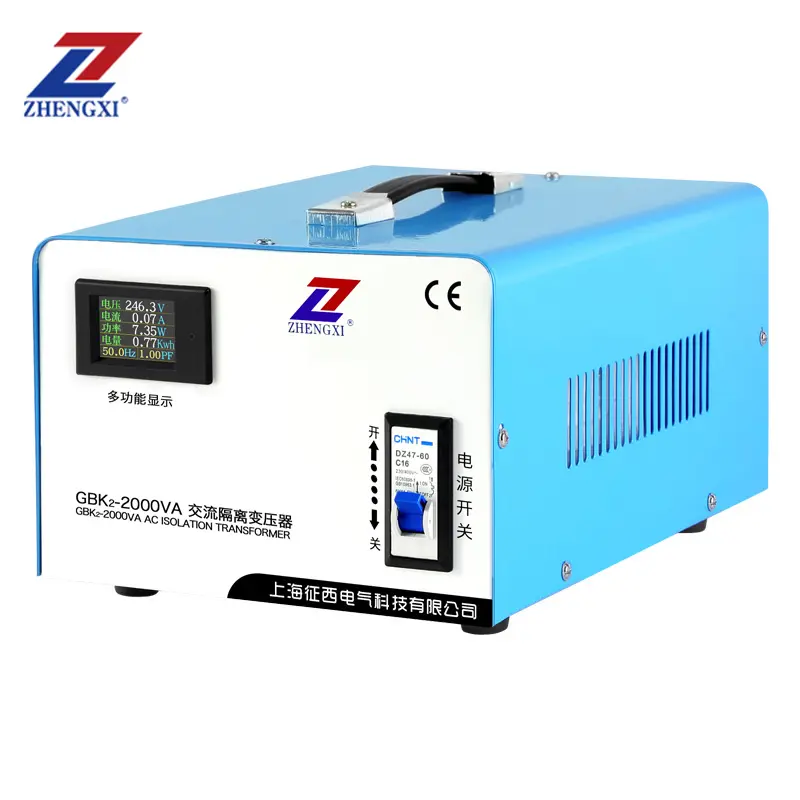
A verificação mais rápida e não intrusiva é a placa de identificação do transformador e a folha de dados que o acompanha. Procure indicadores claros:
- Tensões primária e secundária (por exemplo, 230 V : 230 V) e a classificação kVA.
- Uma redação explícita como "Transformador de isolamento"ou uma especificação 1:1 quando o isolamento é o objetivo da unidade.
- Grupo vetorial ou diagrama de ligação e classe de isolamento (F/H).
- Referências de teste de fábrica (hi-pot, resistência de isolamento) listadas ou disponíveis a pedido.
A placa de identificação, por si só, não é definitiva, mas é a primeira e necessária prova.
2. Indícios visuais e de cablagem na unidade
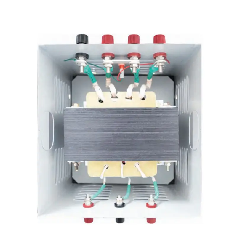
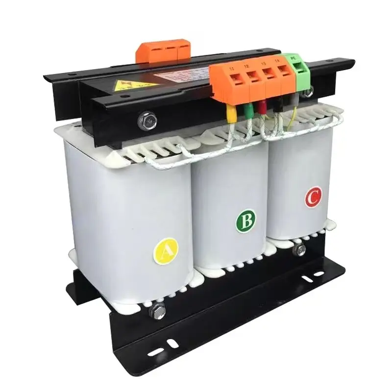
Os transformadores de isolamento têm normalmente blocos de terminais separados e claramente identificados para o ensino primário e secundário. Sinais adicionais: um terminal de proteção/terra (para ecrãs electrostáticos), compartimentos de caixa separados e barreiras de isolamento robustas. Se os terminais estiverem ligados entre si ou partilharem o mesmo bloco, tratar essa unidade com desconfiança.
3. Controlo da continuidade (rápido, seguro e não destrutivo)
Importante: desligue sempre a alimentação e aplique o bloqueio/etiquetagem antes de efetuar testes.
Utilizando um multímetro digital no modo ohms, verifique a continuidade entre qualquer terminal primário e qualquer terminal secundário. Para um transformador de isolamento genuíno, deve ler-se sem continuidade (circuito aberto). Uma leitura de baixa resistência significa que os enrolamentos estão diretamente ligados - a unidade não está isolada.
4. Ensaio de resistência do isolamento (megger) - verificação no terreno
Um teste de resistência de isolamento (megger) mede o grau de isolamento do primário e do secundário. Meça MΩ entre o primário e o secundário e entre cada enrolamento e a terra. Os valores aceitáveis estão tipicamente na ordem dos megaohm comparar com a folha de dados do fabricante. Uma baixa resistência de isolamento indica um isolamento entre enrolamentos comprometido.
5. Teste do rácio de rotação (TTR) - confirma a correção do enrolamento
Um medidor de relação de transformação verifica a relação esperada entre o primário e o secundário. Para transformadores de isolamento 1:1, o TTR deve estar próximo de 1,0. Desvios significativos podem indicar curtos-circuitos, cablagem incorrecta ou falhas de fabrico.
6. Ensaio Hi-pot (dielétrico) - prova definitiva (apenas pessoal treinado)
Os ensaios de elevado potencial aplicam uma tensão elevada controlada de CA ou CC entre o primário e o secundário para validar a resistência do isolamento. Este teste tem de ser efectuado por técnicos com formação, seguindo as normas (IEC/UL/códigos locais). Fazer não O hi-pot no local sem os procedimentos adequados - pode causar tensão no isolamento se for feito incorretamente.
7. Pedir provas documentais (lista de controlo EEAT)
Para comprovar o desempenho do isolamento e apoiar as decisões de aquisição, solicitar:
- Relatórios de testes de isolamento e de potências elevadas da fábrica.
- TTR e relatórios de ensaios de aumento de temperatura.
- Certificados de conformidade (IEC/UL/CE, conforme necessário).
- Esquemas eléctricos e instruções de instalação.
Lista de controlo rápida do comprador (uma vista)
- Placa de identificação: com a indicação "Isolamento" ou especificação 1:1 ✔
- Terminais primários e secundários separados ✔
- Teste de continuidade: não há continuidade primária a secundária ✔
- Megger: MΩ por folha de dados ✔
- TTR: rácio esperado ✔
- Relatórios de teste e de potência máxima de fábrica ✔
FAQs
Q1 - Um transformador 1:1 pode ainda assim NÃO ser um transformador de isolamento?
Sim. A relação 1:1 indica tensões iguais, mas não garante enrolamentos separados. Confirme sempre a separação através da disposição dos terminais, da continuidade e dos relatórios de teste.
Q2 - Um teste com um megger é suficiente para provar o isolamento?
Um megger é um teste de campo muito eficaz, mas deve ser combinado com TTR e hi-pot (quando necessário) e relatórios de fábrica para uma garantia total.
Q3 - Quem deve efetuar os testes hi-pot e TTR?
Apenas técnicos treinados ou engenheiros de serviço autorizados devem efetuar testes de hi-pot ou TTR, seguindo os procedimentos e normas de segurança.
Precisa de transformadores de isolamento verificados com relatórios de teste de fábrica e comissionamento no local? Contacte a Assistência Técnica da ZHENGXI para obter fichas de dados e documentação de ensaios certificados.
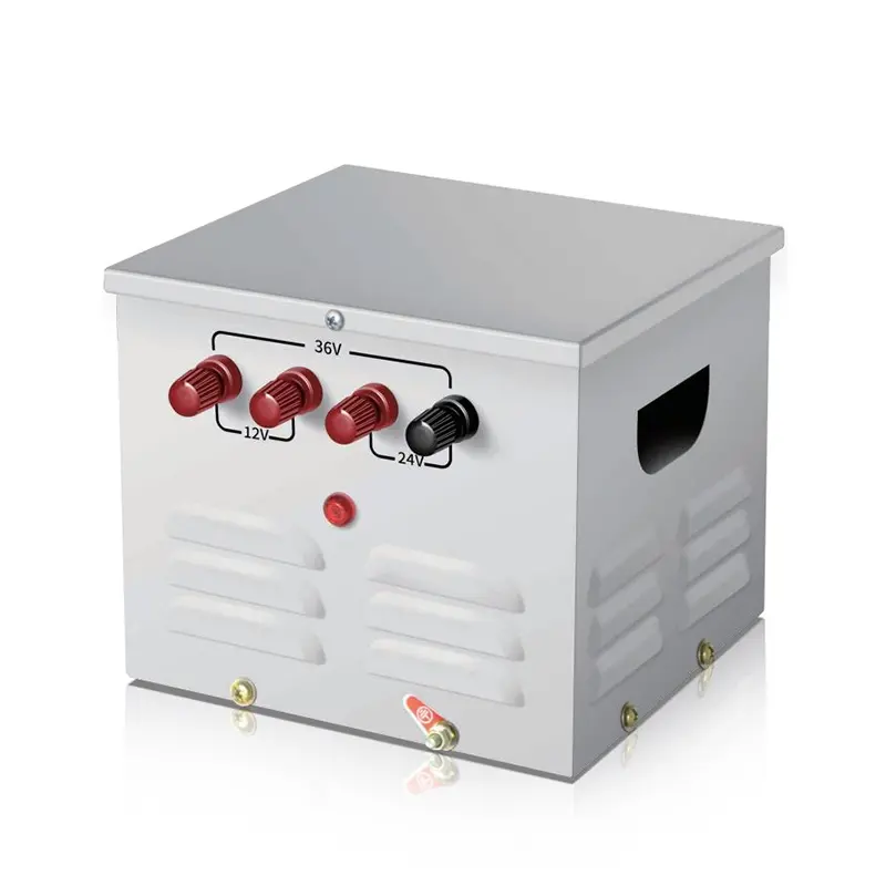
Transformador de isolamento toroidal monofásico 220v a 220v com 2 tomadas de saída
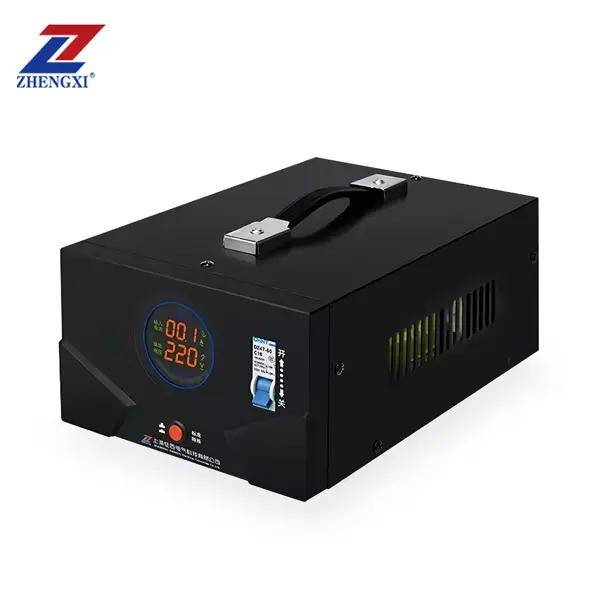
Transformador de controlo de redução de iluminação portátil monofásico JMB 25Va~50Kva
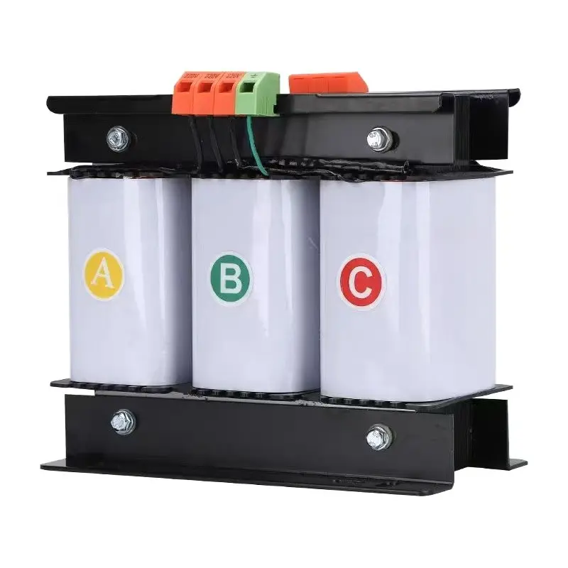
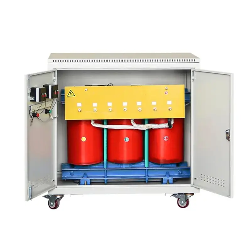
Transformador de controlo trifásico de tipo seco de alta eficiência 500va-1000Kva 415V 400V 380V