


توصيل الأسلاك محول العزل يعد هذا الدليل ضروريًا بشكل صحيح للسلامة وأداء التوافق الكهرومغناطيسي EMC والتشغيل الموثوق به للمعدات النهائية. يرشدك هذا الدليل إلى الخطوات العملية الواعية بالمعايير - ما الذي يجب التحقق منه قبل توصيل الأسلاك، وكيفية إجراء التوصيلات الشائعة أحادية الطور وثلاثية الطور، والاختبارات واحتياطات السلامة التي يجب إجراؤها. استعن دائمًا بفني أو فني كهربائي مؤهل لتنفيذ العمل واتبع القوانين الكهربائية المحلية.
قبل البدء - السلامة والتحقق
- قم بفصل الطاقة وإيقاف التشغيل/الإغلاق/التعليق والتحقق من الجهد الصفري. لا تعمل أبدًا على المحطات الطرفية الأولية/الثانوية المباشرة.
- اقرأ لوحة الاسم وورقة البيانات. قم بتأكيد الفولتية الأولية/الثانوية، والكيلو فولت أمبير، ومجموعة المتجهات، وفئة العزل، والتيار المقنن وتحديد الطرفية.
- تحقق من بيئة التثبيت. حدود التهوية المناسبة، والخلوص، ودرجة الحرارة المحيطة والارتفاع حسب ورقة البيانات.
- اجمع الأدوات ومعدات الحماية الشخصية. مقياس معايرة، ومقياس ميغر، وجهاز اختبار نسبة الدوران (TTR) (إن وجد)، ومفتاح عزم الدوران، وعروات ذات تصنيف صحيح، وقفازات عازلة، وواقي للعينين.
- حدد الكابلات وأجهزة الحماية الصحيحة. مقياس الكابلات، والقواطع/الصمامات والمرحلات الواقية ذات المقاسات المناسبة للتيار المقنن وخصائص التدفق.
محول العزل أحادي الطور - الأسلاك المشتركة (خطوة بخطوة)
الاستخدام النموذجي: 230 فولت → 230 فولت → 230 فولت 1:1 عزل، أو أحمال أحادية الطور أحادية الطور.
- تحديد المحطات الطرفية. عادةً ما تسمى الأطراف الرئيسية H1 / H2 (أو L / N). ثانوية تحمل العلامة X1 / X2 (أو L '/ N'). طرف أرضي/درع موسوم ب PE أو "درع".
- توصيل الإمداد الأساسي. قم بتوصيل وصلة التوصيل المباشر (L) بالوصلة H1 والوصلة المحايدة (N) بالوصلة H2 وفقًا للوحة الاسم. أحكم ربط الأطراف حسب عزم دوران المصنع.
- وصِّل الأرض الواقية. اربط إطار المحول وطرف PE المخصص بالأرض الواقية بالموقع. إذا كان الدرع الكهروستاتيكي موجودًا، فقم بتوصيل طرف التصريف الخاص به بالأرض وفقًا لتعليمات الشركة المصنعة.
- قم بتوصيل الحمل الثانوي. وصِّل الحمل المباشر بـ X1 والمحايد بـ X2. إذا كان المحول 1:1 للعزل، يمكنك اختيار ترك المحول الثانوي غير مؤرضة (عائم) للحصول على أقصى قدر من العزل، أو تأريض المحايد الثانوي إذا كان التركيب يتطلب محايدًا صلبًا - فقط وفقًا لما يمليه التطبيق والرمز المحلي.
- قم بتركيب حماية ضد التيار الزائد. ضع الصمامات أو القواطع على الجانب الابتدائي بحجم مناسب للتيار الابتدائي المقدر للمحول؛ ضع في اعتبارك الحماية الثانوية عند الاقتضاء.
- تحقق من الأسلاك. فحص الاستمرارية (غير مفعل): تأكد من عدم وجود استمرارية ابتدائية أولية ثانوية. اختبار ميجر حسب ورقة البيانات إذا لزم الأمر. يؤكد TTR النسبة.
مهم: لا تُنشئ روابط محايدة/أرضية متوازية على الوصلات الثانوية دون الرجوع إلى تصميم النظام - فقد يؤدي ذلك إلى إبطال العزل وإنشاء حلقات أرضية.
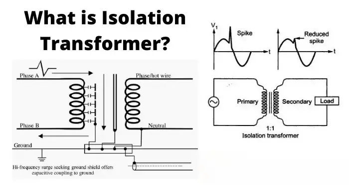
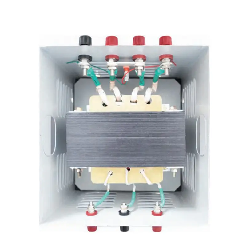
محول العزل ثلاثي الأطوار - أوضاع التوصيل الشائعة وملاحظات الأسلاك
غالبًا ما يتم توصيل محولات العزل ثلاثية الطور سلكيًا في Y (نجمة) أو Δ (دلتا) التكوينات ويمكن توصيلها على شكل Y-Y أو Y-Δ أو Δ-Y، إلخ. يؤثر اختيارك على إزاحة الطور (المجموعة المتجهة) وما إذا كان المحايد متاحًا.
- تأكيد مجموعة المتجهات (ترميز الساعة). ستظهر لوحة الاسم على سبيل المثال، Dyn11، Yyn0. هذا يحدد علاقة الطور بين الابتدائي والثانوي وما إذا كان المحايد قد تم إخراجه. لا تخلط الأطوار بمجموعات متجهات غير متطابقة - فهذا يسبب تيارات دائرية وتلف.
- أمثلة على الأسلاك:
- Y-Y مع محايد (Yyn0): المراحل الابتدائية إلى H1/H2/H3، والمحايد الابتدائي إلى Hn. الأطوار الثانوية إلى X1/X2/X3، والمحايد الثانوي Xn الثانوي مؤرض إذا لزم الأمر. جيد عندما يكون المحايد مطلوبًا على كلا الجانبين ولا يوجد تحول في الطور.
- Δ- Y (D-y) التنحي التدريجي مع محايد على الثانوي (Dyn11): دلتا أساسية (بدون محايد)، نجمة ثانوية مع توفر محايد - تُستخدم عادةً لإنشاء محايد مؤرض على الثانوي.
- التأريض والدروع: في حالة وجود درع كهروستاتيكي (شاشة)، قم بتوصيل الدرع بالأرض فقط، وفقًا لتعليمات الشركة المصنعة - وهذا يمنع تداخل الوضع الشائع مع الحفاظ على العزل الجلفاني.
- الأسلاك المتسلسلة والمراحل: عند التوصيل، تأكد من تسلسل الطور الصحيح. استخدم جهاز اختبار دوران الطور للتأكد من الاتجاه الصحيح قبل التنشيط.
الاختبارات والتشغيل التجريبي (مفصول عن العمل ومفصول عن الطاقة)
- التحقق من الاستمرارية (غير نشط): يجب أن تكون القراءة من الابتدائي إلى الثانوي مفتوحة.
- مقاومة العزل (ميجر): تحقق من MΩ بين اللفات وإلى الأرض حسب ورقة البيانات.
- اختبار نسبة الدوران (TTR): تأكيد نسبة اللفات الصحيحة واكتشاف اللفات القصيرة.
- اختبار هاي بوت (العازل الكهربائي): فقط من قبل موظفين مؤهلين يتبعون المعايير إذا لزم الأمر.
- عدم تنشيط ومراقبة عدم التحميل: تنشيط بدون حمولة؛ قم بقياس الفولتية والفولتية المحايدة/الأرضية وابحث عن أي تسخين أو صوت غير متوقع.
- اختبار التحميل: تطبيق الحمل المتوقع والتحقق من ارتفاع درجة الحرارة وإعدادات رحلة التنظيم والحماية.
أفضل الممارسات ونصائح التثبيت
- الاستخدام عزم الدوران الصحيح على جميع التوصيلات الطرفية لتجنب السخونة الزائدة.
- توفير ملصقات واضحة للطرفين الابتدائي/الثانوي ونقاط التأريض.
- احتفظ الموصلات الأولية والثانوية مفصولة ماديًا لتقليل الاقتران المستحث وتسهيل الصيانة.
- بالنسبة للمعدات الحساسة للضوضاء، استخدم محولًا مزودًا ب الدرع الكهروستاتيكي واتبع تعليمات التأريض بعناية.
- احتفظ بمخططات الأسلاك الخاصة بالشركة المصنعة وتقارير اختبار المصنع مع الوحدة.
الامتثال والمسؤولية
اتبع دائمًا الرموز الكهربائية المحلية (IEC أو NEC أو ما يعادلها إقليميًا)، ودليل التركيب الخاص بالشركة المصنعة، وقواعد التأريض في الموقع. إذا كان المحول يعمل على تشغيل الأنظمة الطبية أو المعملية أو أنظمة السلامة الحرجة، أصر على شهادات اختبار المصنع وفنيي التركيب المعتمدين.
الأسئلة الشائعة
س1 - هل يجب تأريض المحول الثانوي لمحول العزل؟
هذا يعتمد. يؤدي ترك المحايد الثانوي عائمًا إلى زيادة العزل الجلفاني إلى أقصى حد ولكنه قد يعقد استراتيجيات الأرض الواقية. إذا كانت هناك حاجة إلى محايد لأجهزة أو معدات الحماية، قم بتأريض المحايد الثانوي وفقًا للكود المحلي وإرشادات الشركة المصنعة.
س2 - كيف يمكنني تجنب إزاحة الطور أو التيارات الدوارة في التركيبات ثلاثية الطور؟
طابق المحول مجموعة المتجهات بالضبط لمتطلبات النظام. لا تقم أبدًا بتوصيل المحولات بمجموعات متجهات مختلفة. استخدم توصيلات دلتا/النجم الصحيحة وتأكد من دوران الطور قبل التنشيط.
س3 - من الذي ينبغي له إجراء اختبارات الوعاء المرتفع واختبارات TTR؟
يجب أن يقوم الفنيون المدربون والمعتمدون فقط بإجراء اختبار الوعاء العالي واختبار TTR. تتطلب هذه الاختبارات إجراءات سلامة مناسبة ومعدات معايرة؛ يمكن أن يؤدي الاختبار غير السليم إلى تلف العزل أو خلق مخاطر.
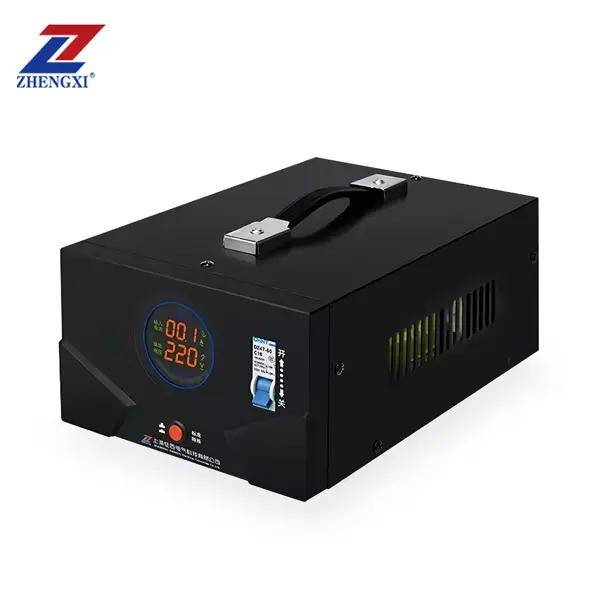
محول عزل حلقي أحادي الطور من 220 فولت إلى 220 فولت مع 2 مقبس إخراج
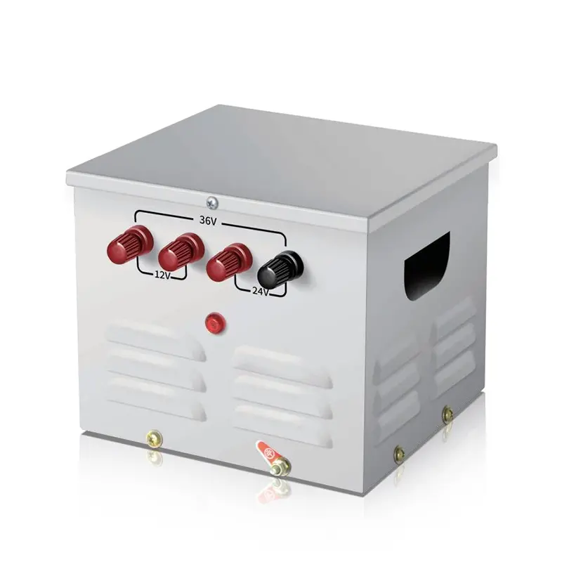
محول التحكم في الإضاءة المحمول أحادي الطور JMB محول التحكم في الإضاءة المتنقل أحادي الطور 25 فولت أمبير ~ 50 كيلو فولت أمبير
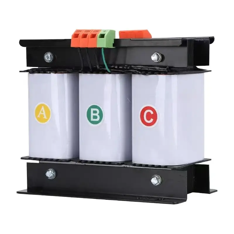
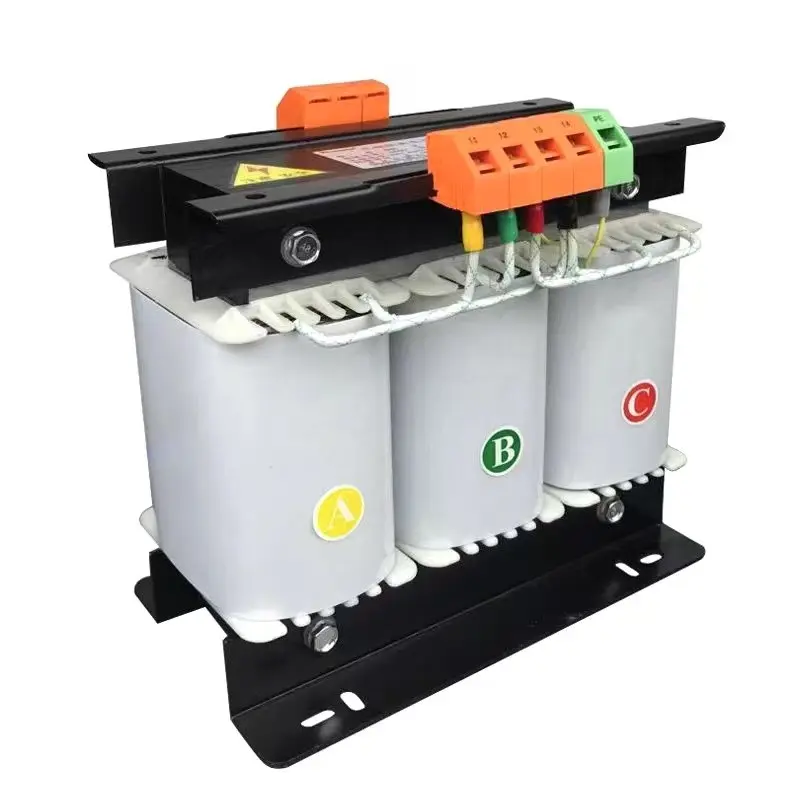
محول تحكم عالي الكفاءة 500 فولت أمبير - 1000 كيلو فولت أمبير ثلاثي الأطوار من النوع الجاف 415 فولت 400 فولت 380 فولت