


Wiring an isolation transformer correctly is essential for safety, EMC performance and reliable operation of downstream equipment. This guide walks you through practical, standards-aware steps—what to check before you wire, how to make common single-phase and three-phase connections, and which tests and safety precautions to perform. Always have a qualified electrician or technician carry out the work and follow local electrical codes.
Before you start — safety & verification
- De-energize, lockout/tagout and verify zero voltage. Never work on live primary/secondary terminals.
- Read the nameplate & datasheet. Confirm primary/secondary voltages, kVA, vector group, insulation class, rated current and terminal identification.
- Check the installation environment. Adequate ventilation, clearance, ambient temp and altitude limits per datasheet.
- Gather tools & PPE. Calibrated meter, megger, TTR (turns-ratio) tester (if available), torque wrench, correct-rated lugs, insulating gloves, eye protection.
- Select correct cabling & protective devices. Cable gauge, breakers/fuses and protective relays sized for rated current and inrush characteristics.
Single-phase isolation transformer — common wiring (step-by-step)
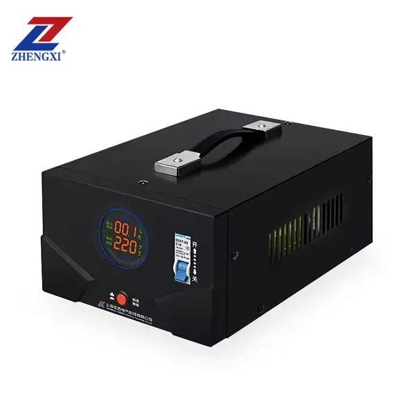
Typical use: 230 V → 230 V 1:1 isolation, or step-down/up single-phase loads.
- Identify terminals. Primary terminals typically labeled H1 / H2 (or L / N). Secondary labeled X1 / X2 (or L’ / N’). Earth/Shield terminal labelled PE or “Shield”.
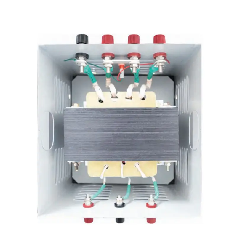
- Connect primary supply. Connect live (L) to H1 and neutral (N) to H2 according to the nameplate. Tighten terminals to manufacturer torque.
- Connect protective earth. Bond the transformer frame and dedicated PE terminal to site protective earth. If an electrostatic shield is present, connect its drain terminal to earth per manufacturer instructions.
- Connect secondary load. Connect load live to X1 and neutral to X2. If the transformer is 1:1 for isolation, you may choose to leave the secondary ungrounded (floating) for maximum isolation, or ground the secondary neutral if a solid neutral is required by the installation—only as dictated by the application and local code.
- Install overcurrent protection. Place fuses or breakers on the primary side sized per transformer’s rated primary current; consider secondary protection where applicable.
- Verify wiring. Continuity check (de-energized): confirm no continuity primary↔secondary. Megger test per datasheet if needed. TTR confirms ratio.
Important: Do not create parallel neutral/earth ties on the secondary without consulting the system design—doing so can defeat isolation and create ground loops.
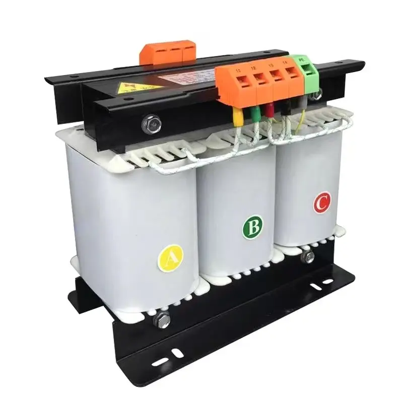
Three-phase isolation transformer — common connection modes & wiring notes
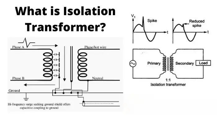
Three-phase isolation transformers are often wired in Y (star) or Δ (delta) configurations and can be connected as Y-Y, Y-Δ, Δ-Y, etc. Your choice affects phase shift (vector group) and whether a neutral is available.
- Confirm vector group (clock notation). Nameplate will show e.g., Dyn11, Yyn0. This defines the phase relationship between primary and secondary and whether a neutral is brought out. Never mix phases with mismatched vector groups—this causes circulating currents and damage.
- Wiring examples:
- Y-Y with neutral (Yyn0): Primary phases to H1/H2/H3, primary neutral to Hn. Secondary phases to X1/X2/X3, secondary neutral Xn grounded if required. Good when neutral required on both sides and no phase shift.
- Δ-Y (D-y) step-down with neutral on secondary (Dyn11): Primary delta (no neutral), secondary star with neutral available—commonly used to create a grounded neutral on secondary.
- Grounding & shields: If electrostatic shield (screen) exists, connect the shield to earth only, per manufacturer instructions—this suppresses common-mode interference while maintaining galvanic isolation.
- Sequential wiring & phasing: When connecting, ensure proper phase sequence. Use a phase rotation tester to confirm correct orientation before energizing.
Tests & commissioning (de-energized & energized)
- Continuity check (de-energized): primary-to-secondary should read open.
- Insulation resistance (megger): verify MΩ between windings and to earth per datasheet.
- Turns-ratio test (TTR): confirm correct turns ratio and detect shorted turns.
- Hi-pot (dielectric) test: only by qualified personnel following standards if required.
- No-load energize & monitor: energize with no load; measure voltages, neutral/earth voltages, and look for unexpected heating or sound.
- Load test: apply expected load and verify temperature rise, regulation and protection trip settings.
Best practices & installation tips
- Use correct torque on all terminal connections to avoid overheating.
- Provide clear labels for primary/secondary terminals and grounding points.
- Keep primary and secondary conductors physically separated to reduce induced coupling and ease maintenance.
- For noise-sensitive equipment, use a transformer with an electrostatic shield and follow grounding instructions carefully.
- Keep manufacturer’s wiring diagrams and factory test reports with the unit.
Compliance & responsibility
Always follow local electrical codes (IEC, NEC, or regional equivalents), manufacturer installation manual, and site earthing rules. If the transformer powers medical, laboratory, or safety-critical systems, insist on factory test certificates and certified installers.
FAQs
Q1 — Should I ground the secondary of an isolation transformer?
It depends. Leaving the secondary floating maximizes galvanic isolation but may complicate protective earth strategies. If a neutral is required for protective devices or equipment, ground the secondary neutral per local code and manufacturer guidance.
Q2 — How do I avoid phase shift or circulating currents in three-phase installations?
Match the transformer’s vector group exactly to system requirements. Never parallel transformers with different vector groups. Use correct delta/star connections and confirm phase rotation before energizing.
Q3 — Who should perform hi-pot and TTR tests?
Only trained, authorized technicians should perform hi-pot and TTR testing. These tests require proper safety procedures and calibrated equipment; improper testing can damage insulation or create hazards.
Single Phase Toroidal Isolation Transformer 220v To 220v With 2 Output Sockets
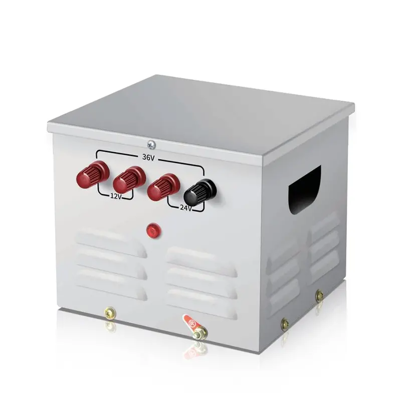
JMB Single-Phase Portable Lighting Step Down Control Transformer 25Va~50Kva
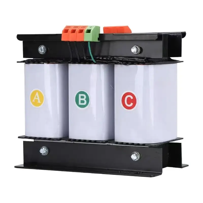
High-Efficiency 500va-1000Kva Three Phase Dry Type Control Transformer 415V 400V 380V