


En transformador de aislamiento proporciona separación galvánica entre sus devanados primario y secundario. Esta separación eléctrica mejora la seguridad, reduce el ruido en modo común y las interferencias del bucle de tierra, y protege los equipos sensibles. Antes de la instalación, las pruebas o la adquisición, es importante poder confirmar que una unidad es un verdadero transformador de aislamiento - no un autotransformador o un transformador de control diferente. Esta guía ofrece medidas de seguridad probadas sobre el terreno y la documentación que debe exigir a los proveedores.
1. Compruebe primero la placa de características y la hoja de datos
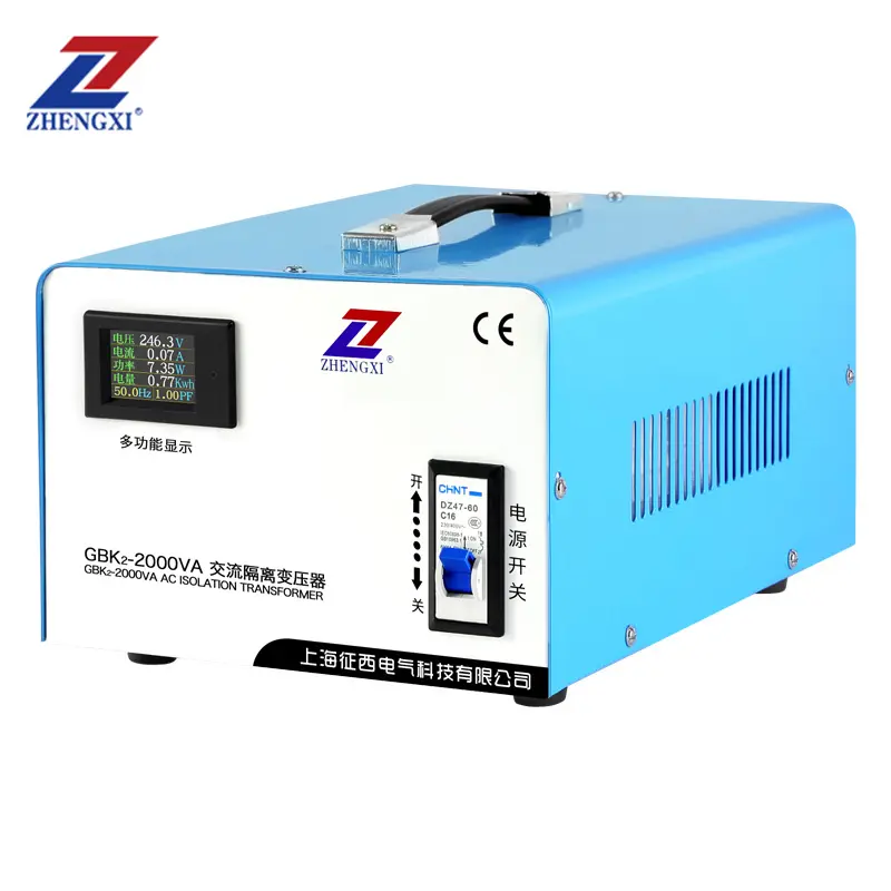
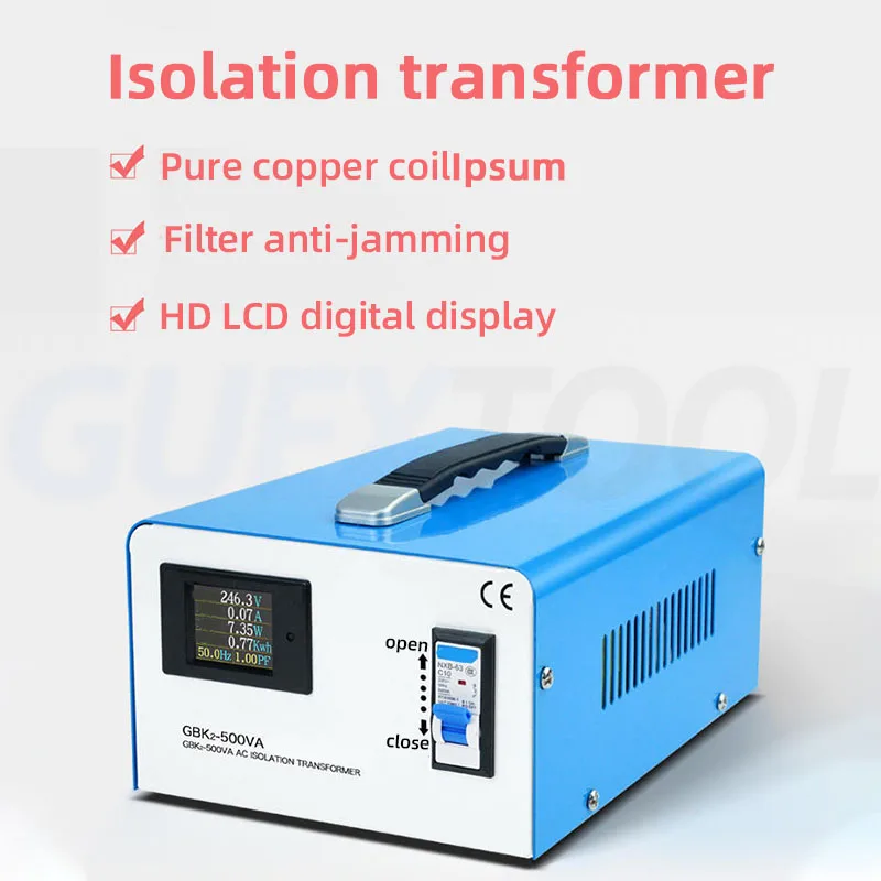
La comprobación más rápida y no intrusiva es la placa de características del transformador y la hoja de datos que la acompaña. Busque indicadores claros:
- Tensión primaria y secundaria (por ejemplo, 230 V : 230 V) y la potencia en kVA.
- Términos explícitos como "Transformador de aislamiento"o una especificación 1:1 cuando la finalidad de la unidad sea el aislamiento.
- Grupo vectorial o diagrama de conexión y clase de aislamiento (F/H).
- Referencias de pruebas de fábrica (hi-pot, resistencia de aislamiento) enumeradas o disponibles a petición.
Una placa de identificación por sí sola no es definitiva, pero es la primera prueba necesaria.
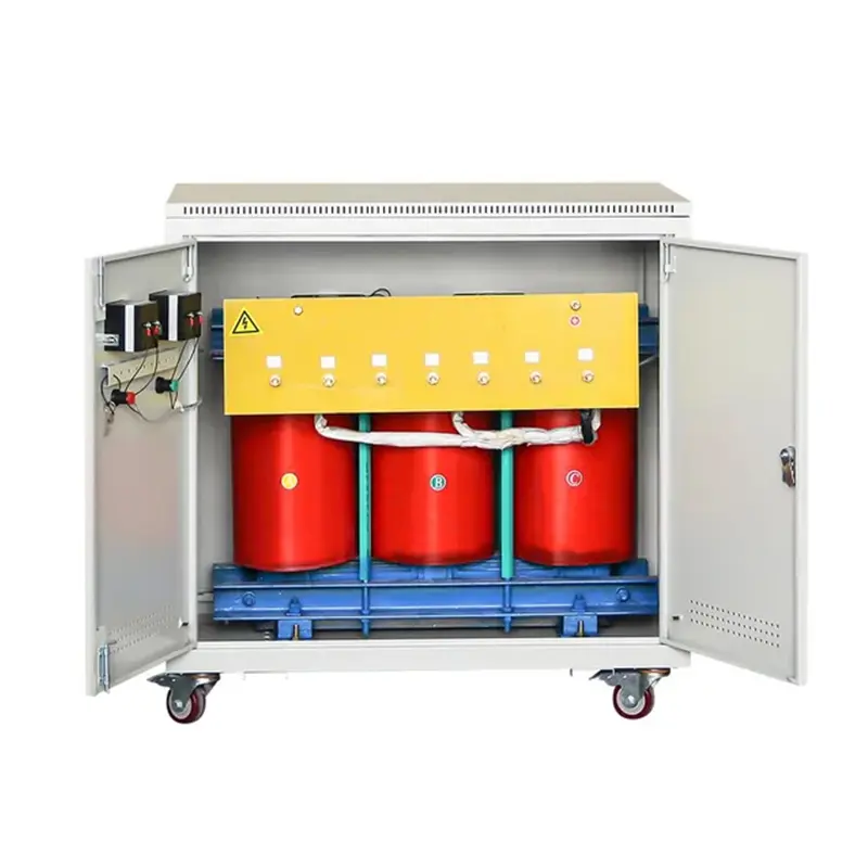
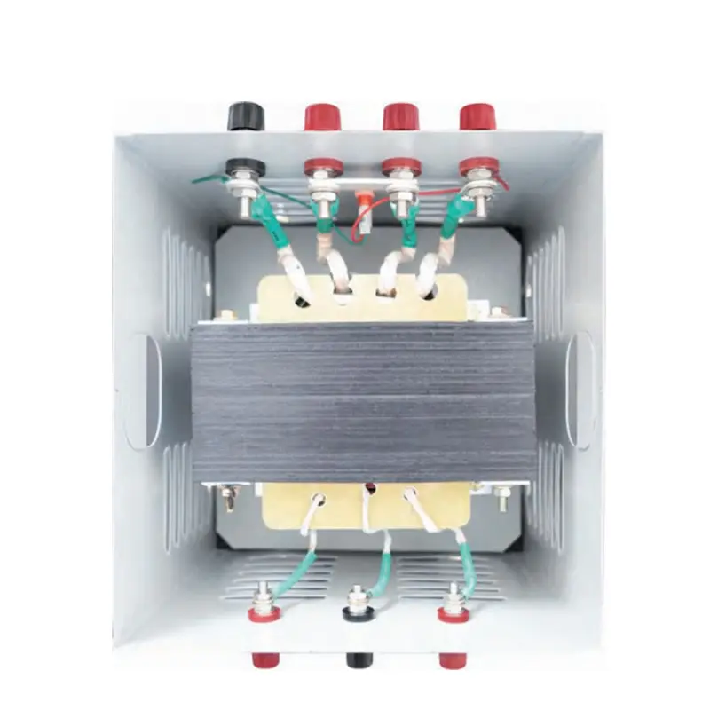
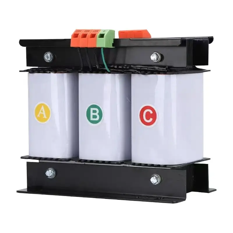
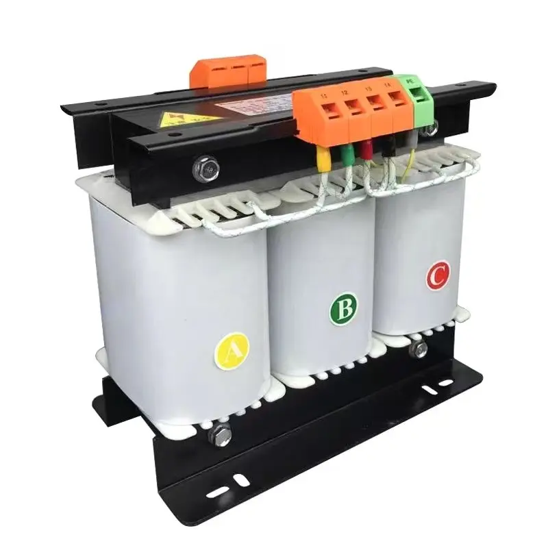
2. Pistas visuales y de cableado de la unidad
Los transformadores de aislamiento suelen tener bloques de terminales separados y claramente etiquetados para primaria y secundaria. Señales adicionales: un blindaje/terminal de tierra (para pantallas electrostáticas), compartimentos separados y robustas barreras aislantes. Si los terminales están unidos o comparten el mismo bloque, trate esa unidad con recelo.
3. Comprobación de continuidad (rápida, segura y no destructiva)
Importante: desconecte siempre la alimentación y aplique el bloqueo/etiquetado antes de realizar las pruebas.
Utilizando un multímetro digital en modo ohmios, compruebe la continuidad entre cualquier terminal primario y cualquier terminal secundario. Para un auténtico transformador de aislamiento debe leer sin continuidad (circuito abierto). Una lectura de resistencia baja significa que los bobinados están conectados directamente, es decir, que la unidad no está aislada.
4. Prueba de resistencia del aislamiento (megger) - verificación sobre el terreno
Una prueba de resistencia de aislamiento (megger) mide lo bien aislados que están el primario y el secundario. Mida MΩ entre el primario y el secundario y entre cada bobinado y tierra. Los valores aceptables suelen estar en el megaohmios comparar con la hoja de datos del fabricante. Una resistencia de aislamiento baja indica que el aislamiento entre devanados está deteriorado.
5. Prueba de relación de vueltas (TTR): confirma la corrección del bobinado.
Un comprobador de relación de transformación verifica la relación esperada entre el primario y el secundario. Para los transformadores de aislamiento 1:1, la TTR debe ser cercana a 1,0. Las desviaciones significativas pueden indicar espiras cortocircuitadas, cableado incorrecto o fallos de fabricación.
6. Prueba Hi-pot (dieléctrica) - prueba definitiva (sólo personal cualificado)
La prueba de alto potencial aplica una alta tensión controlada de CA o CC entre el primario y el secundario para validar la resistencia del aislamiento. Esta prueba debe ser realizada por técnicos cualificados siguiendo las normas (IEC/UL/códigos locales). Consulte no hi-pot in situ sin los procedimientos adecuados - puede estresar el aislamiento si se hace incorrectamente.
7. Pedir pruebas documentadas (lista de comprobación EEAT)
Para demostrar el rendimiento del aislamiento y respaldar las decisiones de contratación, solicite:
- Informes de pruebas de fábrica de alta potencia y aislamiento.
- TTR e informes de pruebas de aumento de temperatura.
- Certificados de conformidad (IEC/UL/CE según se requiera).
- Esquemas eléctricos e instrucciones de instalación.
Lista de comprobación rápida del comprador (una vista)
- Placa de características: etiquetado "Aislamiento" o especificación 1:1 ✔
- Terminales primario y secundario separados ✔
- Prueba de continuidad: no hay continuidad primaria-secundaria ✔
- Megger: MΩ según hoja de datos ✔
- TTR: ratio esperado ✔
- Hi-pot de fábrica e informes de pruebas ✔
Preguntas frecuentes
P1 - ¿Puede un transformador 1:1 NO ser un transformador de aislamiento?
Sí. La relación 1:1 indica tensiones iguales pero no garantiza devanados separados. Confirme siempre la separación mediante la disposición de los terminales, la continuidad y los informes de prueba.
P2 - ¿Es suficiente una prueba megger para demostrar el aislamiento?
Un megger es una prueba de campo sólida, pero debe combinarse con TTR y hi-pot (cuando sea necesario) además de los informes de fábrica para una garantía total.
P3 - ¿Quién debe realizar las pruebas de hi-pot y TTR?
Sólo técnicos formados o ingenieros de servicio autorizados deben realizar pruebas de alta potencia o TTR, siguiendo los procedimientos y normas de seguridad.
¿Necesita transformadores de aislamiento verificados con informes de pruebas de fábrica y puesta en servicio in situ? Póngase en contacto con el servicio técnico de ZHENGXI para obtener hojas de datos y documentación de pruebas certificadas.
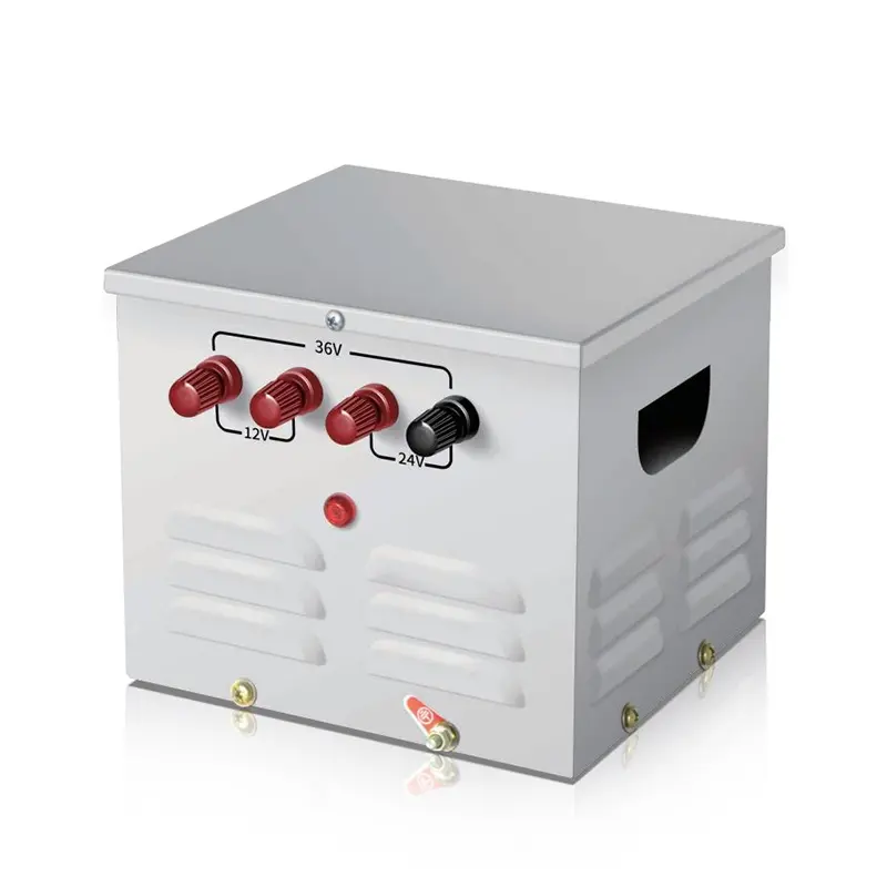
Transformador monofásico toroidal de aislamiento 220v a 220v con 2 tomas de salida
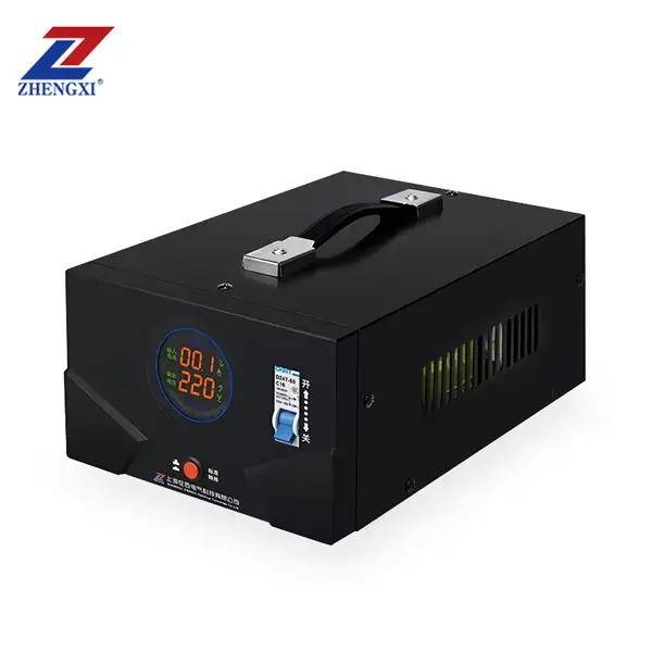
Transformateur de contrôle monophasé portable JMB pour éclairage, abaisseur de tension, 25 VA à 50 kVA
Transformateur de contrôle triphasé sec haute efficacité 500 VA–1000 kVA, 415 V / 400 V / 380 V