


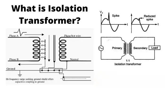
Cableado de un transformador de aislamiento correctamente es esencial para la seguridad, la compatibilidad electromagnética y el funcionamiento fiable de los equipos aguas abajo. Esta guía le guiará a través de pasos prácticos y adaptados a las normas: qué debe comprobar antes de realizar el cableado, cómo realizar las conexiones monofásicas y trifásicas habituales y qué pruebas y precauciones de seguridad debe tomar. Encargue siempre el trabajo a un electricista o técnico cualificado y respete los códigos eléctricos locales.
Antes de empezar - seguridad y verificación
- Desactivar, bloquear/etiquetar y verificar la tensión cero. No trabaje nunca en terminales primarios/secundarios bajo tensión.
- Lea la placa de características y la hoja de datos. Confirme las tensiones primarias/secundarias, los kVA, el grupo vectorial, la clase de aislamiento, la intensidad nominal y la identificación de los bornes.
- Compruebe el entorno de instalación. Ventilación adecuada, espacio libre, temperatura ambiente y límites de altitud según la hoja de datos.
- Reúna las herramientas y los EPI. Medidor calibrado, megóhmetro, comprobador TTR (relación de vueltas) (si se dispone de él), llave dinamométrica, terminales con el calibre correcto, guantes aislantes, protección ocular.
- Seleccione el cableado y los dispositivos de protección adecuados. Calibre de los cables, disyuntores/fusibles y relés de protección dimensionados para la corriente nominal y las características de irrupción.
Transformador monofásico de aislamiento - cableado común (paso a paso)
Uso típico: Aislamiento 230 V → 230 V 1:1, o cargas monofásicas reductoras/elevadoras.
- Identificar terminales. Los bornes primarios suelen estar etiquetados como H1 / H2 (o L / N). Los secundarios etiquetados X1 / X2 (o L' / N'). Terminal de tierra/protección etiquetado como PE o "Shield".
- Conectar la alimentación primaria. Conecte la tensión (L) a H1 y el neutro (N) a H2 de acuerdo con la placa de características. Apriete los terminales con el par de apriete del fabricante.
- Conectar la tierra de protección. Conecte el bastidor del transformador y el terminal PE dedicado a la toma de tierra de protección del emplazamiento. Si hay una pantalla electrostática, conecte su terminal de drenaje a tierra siguiendo las instrucciones del fabricante.
- Conecte la carga secundaria. Conecte la carga a X1 y el neutro a X2. Si el transformador es 1:1 para aislamiento, puede optar por dejar el secundario sin conexión a tierra (flotante) para un aislamiento máximo, o conecte a tierra el neutro secundario si la instalación requiere un neutro sólido, sólo según dicten la aplicación y el código local.
- Instale una protección contra sobrecorriente. Coloque fusibles o disyuntores en el lado primario dimensionados según la corriente primaria nominal del transformador; considere la protección secundaria cuando proceda.
- Verifique el cableado. Comprobación de continuidad (sin tensión): confirme que no hay continuidad entre el primario y el secundario. Prueba Megger según hoja de datos si es necesario. TTR confirma la relación.
Importante: No conecte neutro/tierra en paralelo en el secundario sin consultar el diseño del sistema, ya que podría anular el aislamiento y crear bucles de tierra.
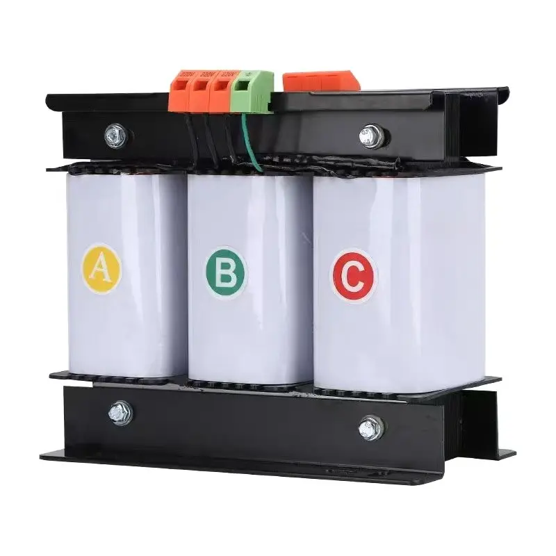
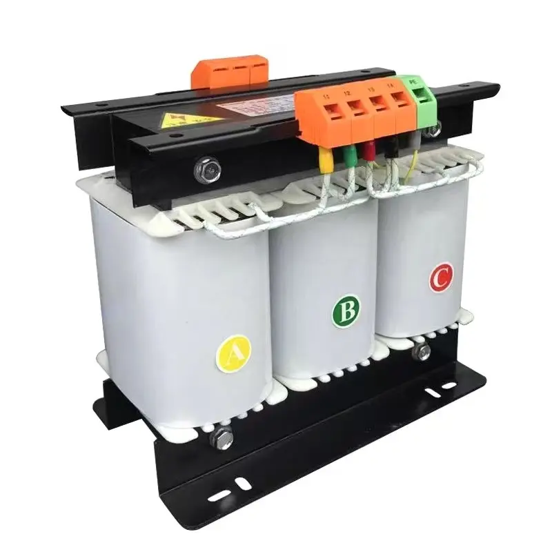
Transformador trifásico de aislamiento - modos de conexión comunes y notas sobre el cableado
Los transformadores trifásicos de aislamiento suelen cablearse en Y (estrella) o Δ (delta) y pueden conectarse como Y-Y, Y-Δ, Δ-Y, etc. Su elección afecta al desplazamiento de fase (grupo vectorial) y a la disponibilidad de neutro.
- Confirmar grupo vectorial (notación reloj). La placa de características mostrará, por ejemplo, Dyn11, Yyn0. Esto define la relación de fase entre el primario y el secundario y si se saca un neutro. Nunca mezcle fases con grupos vectoriales desajustados, ya que esto provoca corrientes circulantes y daños.
- Ejemplos de cableado:
- Y-Y con neutro (Yyn0): Fases primarias a H1/H2/H3, neutro primario a Hn. Fases secundarias a X1/X2/X3, neutro secundario Xn conectado a tierra si es necesario. Bueno cuando se requiere neutro en ambos lados y no hay cambio de fase.
- Reductor Δ-Y (D-y) con neutro en el secundario (Dyn11): Primario en triángulo (sin neutro), secundario en estrella con neutro disponible: se utiliza habitualmente para crear un neutro conectado a tierra en el secundario.
- Puesta a tierra y blindajes: Si existe blindaje electrostático (pantalla), conecte el blindaje sólo a tierra, según las instrucciones del fabricante; de este modo se suprimen las interferencias de modo común y se mantiene el aislamiento galvánico.
- Cableado secuencial y fases: Al realizar la conexión, asegúrese de que la secuencia de fases es correcta. Utilice un comprobador de rotación de fases para confirmar la orientación correcta antes de conectar la alimentación.
Pruebas y puesta en servicio (sin tensión y con tensión)
- Comprobación de continuidad (sin tensión): primario-secundario debe indicar abierto.
- Resistencia de aislamiento (megger): verificar MΩ entre devanados y a tierra según ficha técnica.
- Prueba de relación de vueltas (TTR): confirmar la relación de vueltas correcta y detectar las vueltas en cortocircuito.
- Prueba Hi-pot (dieléctrica): sólo por personal cualificado siguiendo las normas si es necesario.
- Energizar y monitorizar en vacío: energizar sin carga; medir voltajes, voltajes neutro/tierra y buscar calentamiento o sonido inesperado.
- Prueba de carga: aplique la carga prevista y verifique el aumento de temperatura, la regulación y los ajustes de disparo de la protección.
Buenas prácticas y consejos de instalación
- Utilice par correcto en todas las conexiones de los terminales para evitar el sobrecalentamiento.
- Proporcione etiquetas transparentes para terminales primarios/secundarios y puntos de conexión a tierra.
- Visite conductores primario y secundario separados físicamente para reducir el acoplamiento inducido y facilitar el mantenimiento.
- Para equipos sensibles al ruido, utilice un transformador con un pantalla electrostática y siga atentamente las instrucciones de conexión a tierra.
- Conserve los diagramas de cableado del fabricante y los informes de pruebas de fábrica junto con la unidad.
Cumplimiento y responsabilidad
Respete siempre los códigos eléctricos locales (IEC, NEC o equivalentes regionales), el manual de instalación del fabricante y las normas de puesta a tierra del emplazamiento. Si el transformador alimenta sistemas médicos, de laboratorio o críticos para la seguridad, exija certificados de prueba de fábrica e instaladores certificados.
Preguntas frecuentes
P1 - ¿Debo conectar a tierra el secundario de un transformador de aislamiento?
Depende. Dejar el secundario flotante maximiza el aislamiento galvánico pero puede complicar las estrategias de puesta a tierra de protección. Si se requiere un neutro para los dispositivos o equipos de protección, conecte a tierra el neutro secundario de acuerdo con el código local y las directrices del fabricante.
P2 - ¿Cómo evitar el desfase o las corrientes circulantes en instalaciones trifásicas?
Haga coincidir el grupo vectorial exactamente a los requisitos del sistema. Nunca ponga en paralelo transformadores con grupos vectoriales diferentes. Utilice conexiones delta/estrella correctas y confirme la rotación de fases antes de la energización.
P3 - ¿Quién debe realizar las pruebas de hi-pot y TTR?
Las pruebas de alta potencia y TTR sólo deben ser realizadas por técnicos formados y autorizados. Estas pruebas requieren procedimientos de seguridad adecuados y equipos calibrados; las pruebas incorrectas pueden dañar el aislamiento o crear riesgos.
Transformador toroidal de potencia de amplificador de audio variable de calidad personalizada
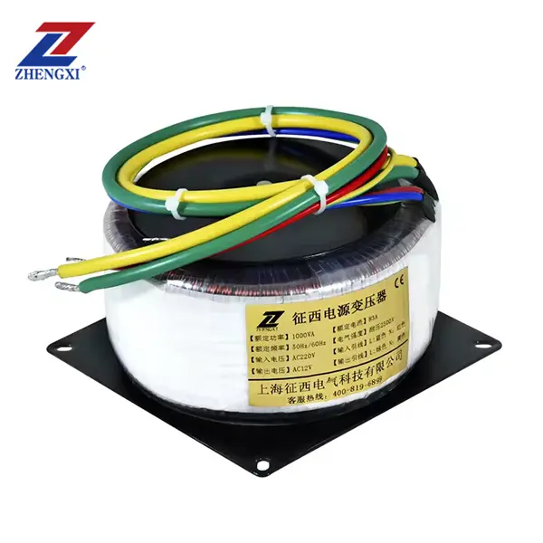
En Transformador toroidal de potencia de amplificador de audio variable de calidad personalizada de ZHENGXI está diseñado para ofrecer una fidelidad de audio y un aislamiento eléctrico excepcionales para sistemas de audio profesionales. Como proveedor de transformadores toroidales, ZHENGXI se especializa en la fabricación transformadores de audio personalizados que garantizan una distorsión mínima, un ruido ultrabajo y una adaptación perfecta de la impedancia, ideales para amplificadores de gama alta, equipos de grabación, sistemas de radiodifusión e ingeniería de sonido de estudio.
A diferencia de los transformadores con núcleo EI convencionales, transformadores toroidales cuentan con un diseño de núcleo circular que proporciona una eficiencia superior, bajas interferencias electromagnéticas (EMI) y una excelente respuesta en frecuencia en todo el espectro de audio de 20 Hz a 20 kHz.
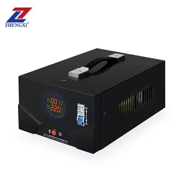
Transformador monofásico toroidal de aislamiento 220v a 220v con 2 tomas de salida
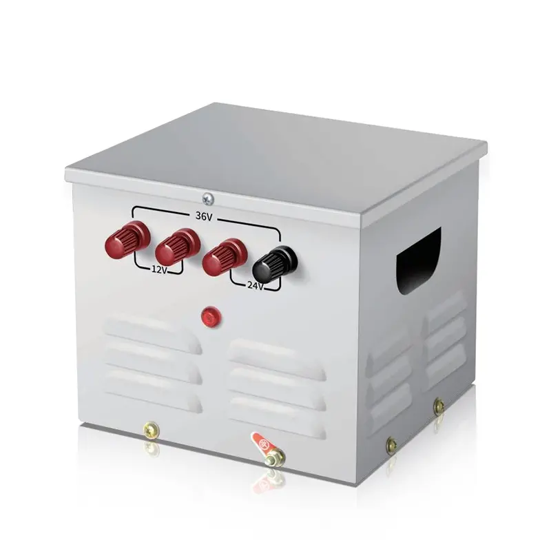
Transformateur de contrôle monophasé portable JMB pour éclairage, abaisseur de tension, 25 VA à 50 kVA