


Un trasformatore di isolamento fornisce una separazione galvanica tra gli avvolgimenti primari e secondari. Questa separazione elettrica migliora la sicurezza, riduce i disturbi di modo comune e le interferenze di massa e protegge le apparecchiature sensibili. Prima di procedere all'installazione, al collaudo o all'approvvigionamento, è importante essere in grado di confermare che un'unità sia un vero trasformatore di isolamento, non un autotrasformatore o un trasformatore di controllo diverso. Questa guida fornisce i passi da seguire per la sicurezza, testati sul campo, e la documentazione da richiedere ai fornitori.
1. Controllare innanzitutto la targhetta e la scheda tecnica.
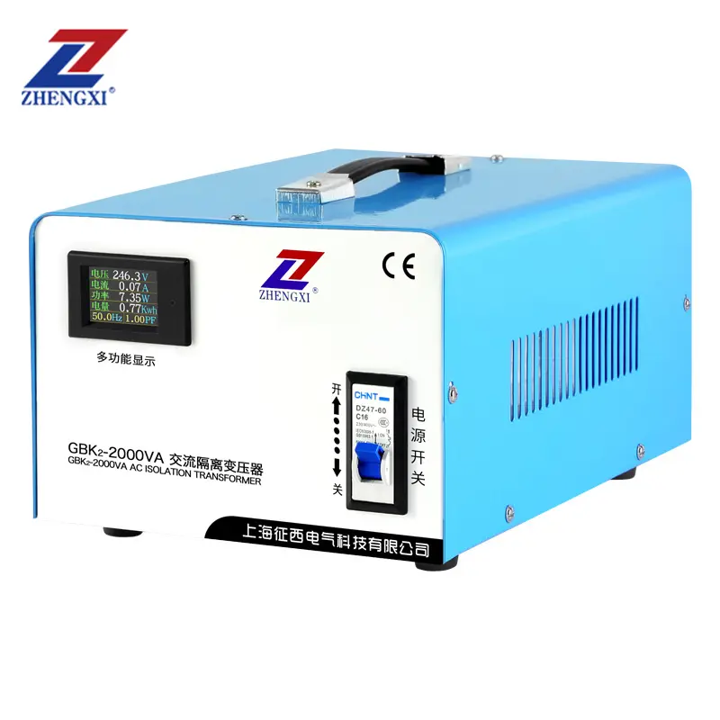
Il controllo più rapido e non invasivo è la targhetta del trasformatore e la relativa scheda tecnica. Cercate indicatori chiari:
- Tensioni primarie e secondarie (ad esempio, 230 V : 230 V) e kVA.
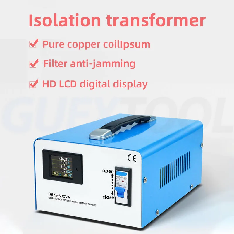
- Una formulazione esplicita come "Trasformatore di isolamento", "Isolante", o una specifica 1:1 quando l'isolamento è lo scopo dell'unità.
- Gruppo vettoriale o diagramma di connessione e classe di isolamento (F/H).
- Riferimenti ai test di fabbrica (hi-pot, resistenza di isolamento) elencati o disponibili su richiesta.
Una targhetta da sola non è definitiva, ma è il primo e necessario elemento di prova.
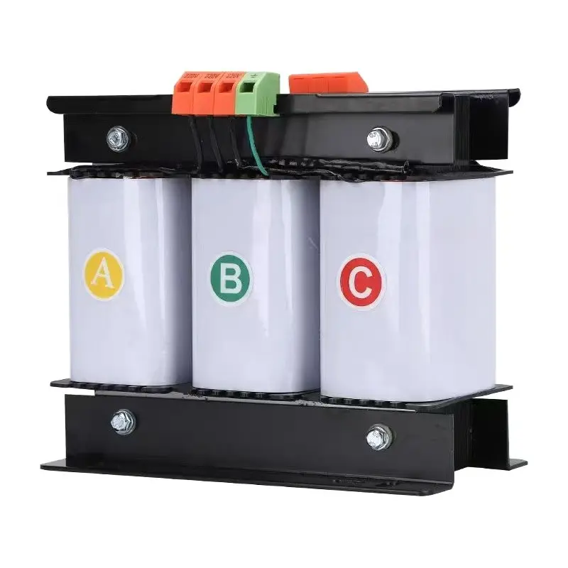
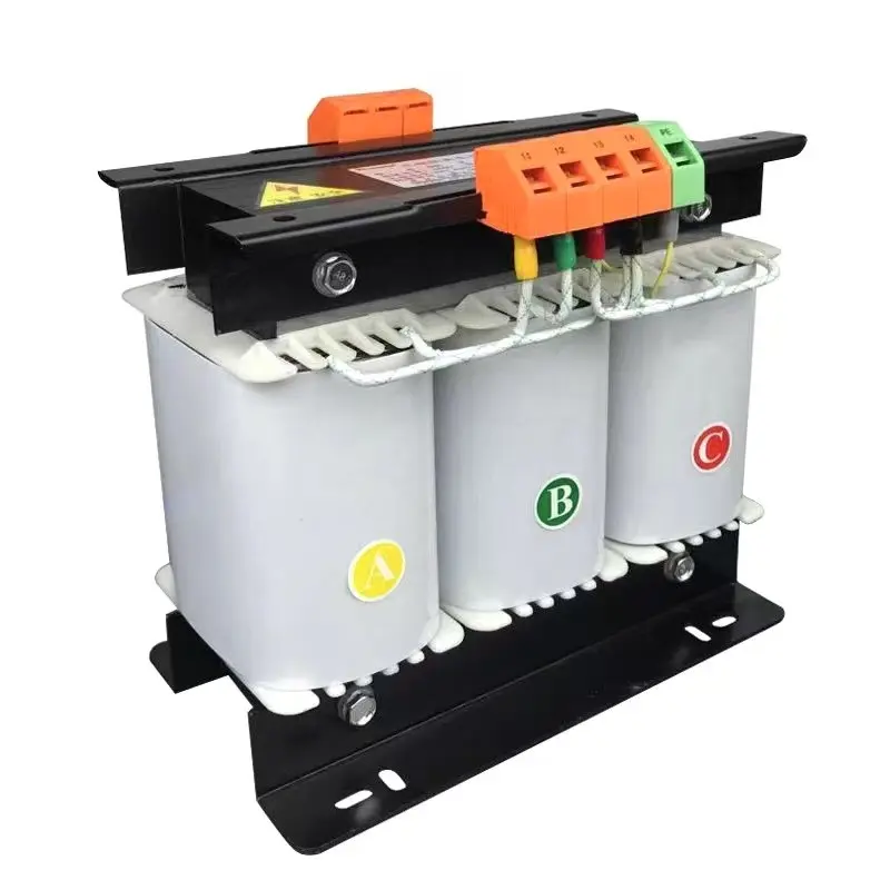
2. Indizi visivi e di cablaggio sull'unità
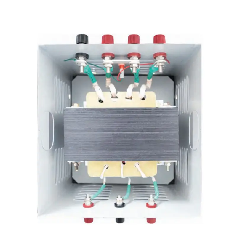
I trasformatori di isolamento hanno tipicamente morsettiere separate e chiaramente etichettate per la primaria e la secondaria. Segnaletica aggiuntiva: un'area dedicata terminale di schermatura/terreno (per gli schermi elettrostatici), compartimenti separati e robuste barriere isolanti. Se i terminali sono collegati tra loro o condividono lo stesso blocco, trattateli con sospetto.
3. Controllo della continuità (rapido, sicuro, non distruttivo)
Importante: scollegare sempre l'alimentazione e applicare il lockout/tagout prima di eseguire il test.
Utilizzando un multimetro digitale in modalità ohm, verificare la continuità tra qualsiasi terminale primario e qualsiasi terminale secondario. Per un trasformatore di isolamento autentico si dovrebbe leggere nessuna continuità (circuito aperto). Una lettura di bassa resistenza significa che gli avvolgimenti sono direttamente collegati - l'unità non è isolata.
4. Test di resistenza dell'isolamento (megger) - verifica sul campo
Il test della resistenza di isolamento (megger) misura il grado di isolamento del primario e del secondario. Misurare MΩ tra primario e secondario e tra ciascun avvolgimento e la terra. I valori accettabili sono in genere compresi tra megaohm gamma; confrontare con la scheda tecnica del produttore. Una bassa resistenza di isolamento indica un isolamento compromesso tra gli avvolgimenti.
5. Test del rapporto di rotazione (TTR): conferma la correttezza dell'avvolgimento.
Un tester per il rapporto di rotazione dei trasformatori verifica il rapporto previsto tra primario e secondario. Per i trasformatori con isolamento 1:1, il TTR dovrebbe essere prossimo a 1,0. Deviazioni significative possono indicare spire in cortocircuito, cablaggio errato o difetti di fabbricazione.
6. Prova Hi-pot (dielettrica) - prova definitiva (solo per personale addestrato)
Il test ad alto potenziale applica un'alta tensione CA o CC controllata tra primario e secondario per verificare la resistenza dell'isolamento. Questo test deve essere eseguito da tecnici qualificati secondo gli standard (IEC/UL/codici locali). Fare non Non è possibile utilizzare l'idropulitrice in loco senza una procedura adeguata: se non è stata eseguita correttamente, l'isolamento può risultare stressante.
7. Chiedere prove documentate (lista di controllo EEAT)
Per dimostrare le prestazioni di isolamento e supportare le decisioni di acquisto, richiedere:
- Rapporti di prova dell'hi-pot e dell'isolamento in fabbrica.
- Rapporti di prova TTR e di aumento della temperatura.
- Certificati di conformità (IEC/UL/CE come richiesto).
- Schemi di cablaggio e istruzioni per l'installazione.
Lista di controllo rapida per l'acquirente (una vista)
- Targa dati: etichettatura "Isolamento" o specifiche 1:1 ✔
- Terminali primari e secondari separati ✔
- Test di continuità: nessuna continuità da primario a secondario ✔
- Megger: MΩ per scheda tecnica ✔
- TTR: rapporto atteso ✔
- Rapporti di prova e hi-pot di fabbrica ✔
Domande frequenti
Q1 - Un trasformatore 1:1 può ancora NON essere un trasformatore di isolamento?
Sì. Il rapporto 1:1 indica tensioni uguali ma non garantisce avvolgimenti separati. Confermare sempre la separazione tramite la disposizione dei terminali, la continuità e i rapporti di prova.
D2 - Un test megger è sufficiente per dimostrare l'isolamento?
Un megger è un test sul campo molto efficace, ma dovrebbe essere combinato con il TTR e l'hi-pot (quando necessario) e con i rapporti di fabbrica per una garanzia completa.
D3 - Chi deve eseguire i test hi-pot e TTR?
L'esecuzione di test hi-pot o TTR deve essere eseguita solo da tecnici qualificati o da ingegneri autorizzati, seguendo le procedure e gli standard di sicurezza.
Avete bisogno di trasformatori di isolamento verificati con rapporti di prova in fabbrica e messa in servizio in loco? Contattate l'assistenza tecnica ZHENGXI per ottenere schede tecniche e documentazione di prova certificata.
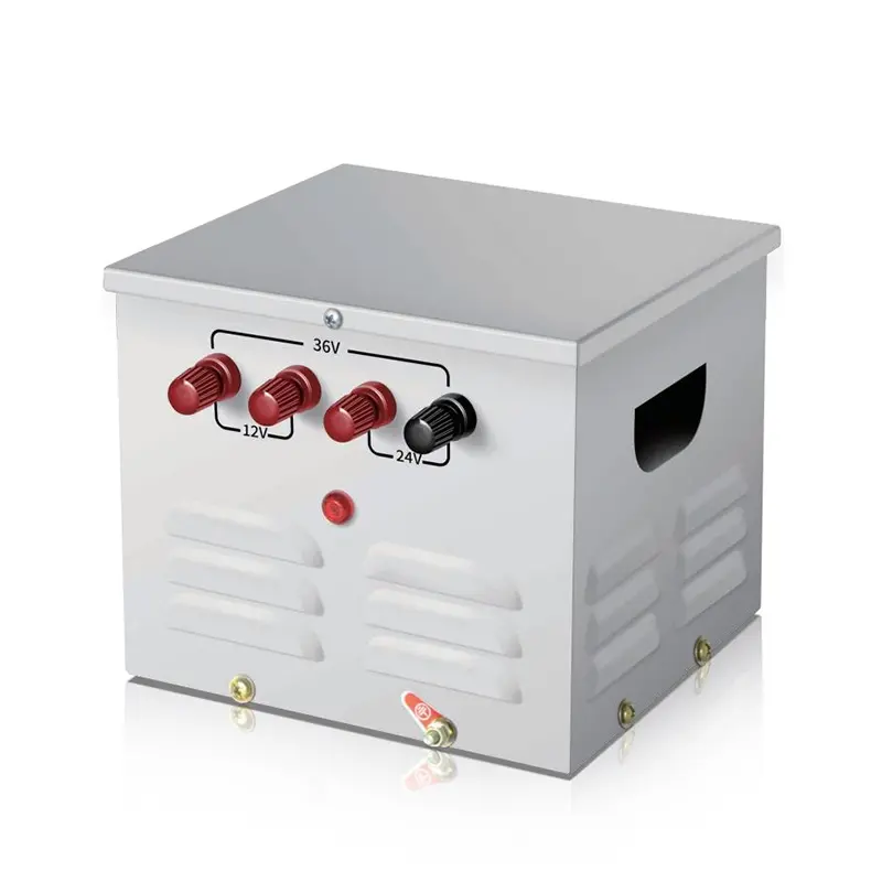
Trasformatore di isolamento toroidale monofase da 220v a 220v con 2 prese di uscita
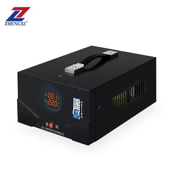
Trasformatore di controllo step-down per illuminazione portatile monofase JMB 25Va~50Kva
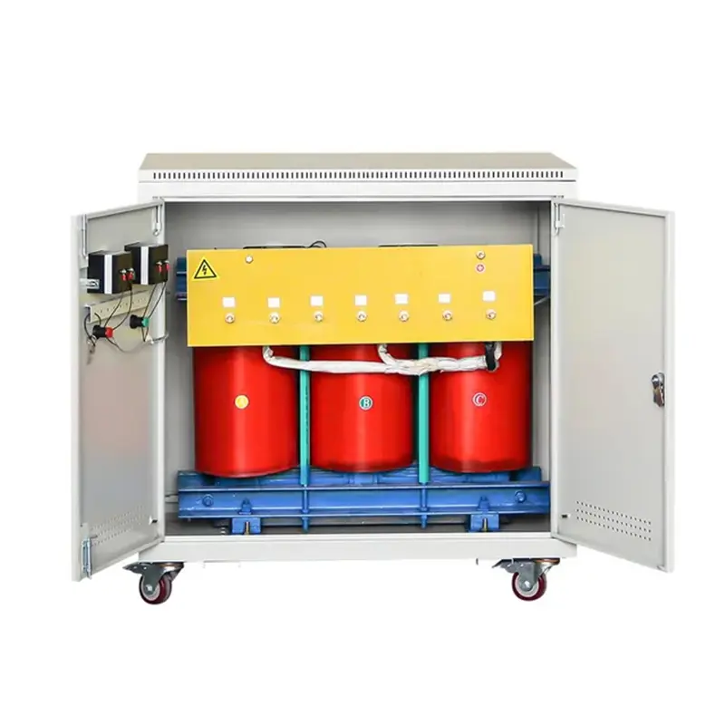
Trasformatore di controllo trifase a secco ad alta efficienza da 500 VA a 1000 KVA 415 V 400 V 380 V