


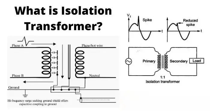
Cablaggio di un trasformatore di isolamento è essenziale per la sicurezza, le prestazioni EMC e il funzionamento affidabile delle apparecchiature a valle. Questa guida vi guida attraverso passi pratici e consapevoli delle norme: cosa controllare prima di cablare, come effettuare i comuni collegamenti monofase e trifase e quali test e precauzioni di sicurezza eseguire. Affidate sempre il lavoro a un elettricista o a un tecnico qualificato e seguite le norme elettriche locali.
Prima di iniziare: sicurezza e verifica
- Disattivare l'alimentazione, bloccare/tagout e verificare l'assenza di tensione. Non lavorare mai sui terminali primari/secondari sotto tensione.
- Leggere la targhetta e la scheda tecnica. Confermare le tensioni primarie/secondarie, i kVA, il gruppo vettoriale, la classe di isolamento, la corrente nominale e l'identificazione dei terminali.
- Controllare l'ambiente di installazione. Ventilazione adeguata, spazio libero, temperatura ambiente e limiti di altitudine come da scheda tecnica.
- Raccogliere gli strumenti e i DPI. Misuratore calibrato, megger, tester TTR (rapporto di rotazione) (se disponibile), chiave dinamometrica, capicorda di dimensioni corrette, guanti isolanti, protezione per gli occhi.
- Selezionare il cablaggio e i dispositivi di protezione corretti. Calibro dei cavi, interruttori/fusibili e relè di protezione dimensionati per la corrente nominale e le caratteristiche di spunto.
Trasformatore d'isolamento monofase - cablaggio comune (passo dopo passo)
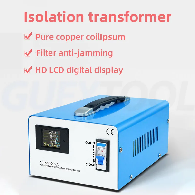
Utilizzo tipico: 230 V → 230 V isolamento 1:1, o carichi monofase step-down/up.
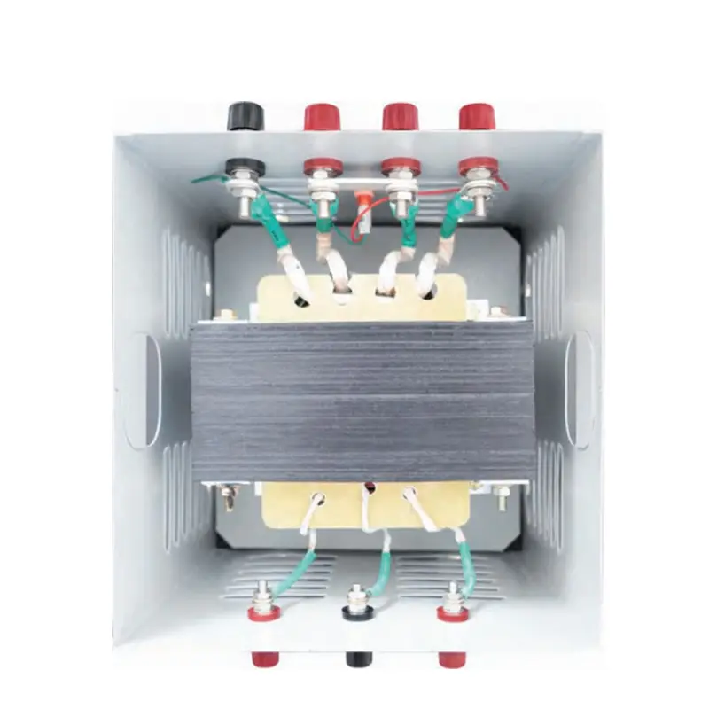
- Identificare i terminali. I terminali primari sono tipicamente etichettati H1 / H2 (o L / N). Secondari etichettati X1 / X2 (o L' / N'). Terminale di terra/schermo etichettato PE o "Shield".
- Collegare l'alimentazione primaria. Collegare la tensione (L) a H1 e il neutro (N) a H2 secondo la targhetta. Serrare i terminali secondo la coppia di serraggio indicata dal produttore.
- Collegare la terra di protezione. Collegare il telaio del trasformatore e il terminale PE dedicato alla terra di protezione del sito. Se è presente uno schermo elettrostatico, collegare il suo terminale di scarico a terra secondo le istruzioni del produttore.
- Collegare il carico secondario. Collegare il carico in tensione a X1 e il neutro a X2. Se il trasformatore è 1:1 per l'isolamento, si può scegliere di lasciare il secondario a X2. non collegato a terra (galleggiante) per il massimo isolamento, oppure mettere a terra il neutro secondario se l'installazione richiede un neutro solido, solo in base all'applicazione e alle norme locali.
- Installare una protezione da sovracorrente. Collocare fusibili o interruttori sul lato primario dimensionati in base alla corrente primaria nominale del trasformatore; considerare la protezione secondaria, se applicabile.
- Verificare il cablaggio. Controllo della continuità (senza tensione): confermare l'assenza di continuità primario↔secondario. Se necessario, eseguire il test Megger secondo la scheda tecnica. TTR conferma il rapporto.
Importante: Non creare legami di neutro/terra in parallelo sul secondario senza aver consultato il progetto dell'impianto: ciò può vanificare l'isolamento e creare loop di terra.
Trasformatore di isolamento trifase - modalità di collegamento comuni e note di cablaggio
I trasformatori d'isolamento trifase sono spesso cablati in Y (stella) o Δ (delta) e possono essere collegati come Y-Y, Y-Δ, Δ-Y, ecc. La scelta influisce sullo sfasamento (gruppo vettoriale) e sulla disponibilità di un neutro.
- Confermare il gruppo di vettori (notazione dell'orologio). La targa dati indicherà, ad esempio, Dyn11, Yyn0. Questo definisce il rapporto di fase tra primario e secondario e l'eventuale presenza di un neutro. Non mescolare mai le fasi con gruppi di vettori non corrispondenti: ciò provoca correnti circolanti e danni.
- Esempi di cablaggio:
- Y-Y con neutro (Yyn0): Fasi primarie a H1/H2/H3, neutro primario a Hn. Fasi secondarie a X1/X2/X3, neutro secondario Xn a terra se necessario. Ottimo quando è richiesto il neutro su entrambi i lati e non c'è sfasamento.
- Δ-Y (D-y) step-down con neutro sul secondario (Dyn11): Primario a triangolo (senza neutro), secondario a stella con neutro disponibile - comunemente usato per creare un neutro a terra sul secondario.
- Messa a terra e schermature: Se esiste una schermatura elettrostatica (schermo), collegare la schermatura solo a terra, secondo le istruzioni del produttore: in questo modo si sopprimono le interferenze di modo comune mantenendo l'isolamento galvanico.
- Cablaggio sequenziale e fasatura: Durante il collegamento, accertarsi della corretta sequenza delle fasi. Utilizzare un tester di rotazione delle fasi per confermare il corretto orientamento prima di dare tensione.
Test e messa in servizio (senza tensione e con tensione)
- Controllo della continuità (diseccitato): il primario-secondario deve risultare aperto.
- Resistenza di isolamento (megger): verificare i MΩ tra gli avvolgimenti e verso terra come da scheda tecnica.
- Test del rapporto di rotazione (TTR): confermare il corretto rapporto tra le spire e rilevare le spire in cortocircuito.
- Test Hi-pot (dielettrico): solo da personale qualificato, seguendo le norme, se necessario.
- Alimentazione e monitoraggio a vuoto: dare tensione a vuoto; misurare le tensioni, le tensioni neutro/terra e verificare che non si verifichino riscaldamenti o rumori inaspettati.
- Prova di carico: applicare il carico previsto e verificare l'aumento di temperatura, la regolazione e le impostazioni di intervento della protezione.
Migliori pratiche e suggerimenti per l'installazione
- Utilizzo coppia corretta su tutti i collegamenti dei terminali per evitare il surriscaldamento.
- Fornire etichette trasparenti per i terminali primario/secondario e i punti di messa a terra.
- Mantenere conduttori primari e secondari fisicamente separati per ridurre l'accoppiamento indotto e facilitare la manutenzione.
- Per le apparecchiature sensibili ai rumori, utilizzare un trasformatore con un schermo elettrostatico e seguire attentamente le istruzioni per la messa a terra.
- Conservare gli schemi di cablaggio del produttore e i rapporti di prova di fabbrica con l'unità.
Conformità e responsabilità
Seguire sempre le norme elettriche locali (IEC, NEC o equivalenti regionali), il manuale di installazione del produttore e le regole di messa a terra del sito. Se il trasformatore alimenta sistemi medici, di laboratorio o critici per la sicurezza, insistete sui certificati di prova della fabbrica e su installatori certificati.
Domande frequenti
Q1 - Devo mettere a terra il secondario di un trasformatore di isolamento?
Dipende. Lasciare il secondario flottante massimizza l'isolamento galvanico, ma può complicare le strategie di messa a terra. Se è necessario un neutro per i dispositivi o le apparecchiature di protezione, mettere a terra il neutro secondario secondo le norme locali e le indicazioni del produttore.
D2 - Come si evitano gli sfasamenti o le correnti circolanti nelle installazioni trifase?
Abbinare il trasformatore gruppo di vettori esattamente ai requisiti del sistema. Non mettere mai in parallelo trasformatori con gruppi vettoriali diversi. Utilizzare collegamenti a triangolo/stella corretti e verificare la rotazione delle fasi prima di dare tensione.
D3 - Chi deve eseguire i test hi-pot e TTR?
I test hi-pot e TTR devono essere eseguiti solo da tecnici qualificati e autorizzati. Questi test richiedono procedure di sicurezza adeguate e apparecchiature calibrate; test impropri possono danneggiare l'isolamento o creare pericoli.

Trasformatore di isolamento toroidale monofase da 220v a 220v con 2 prese di uscita
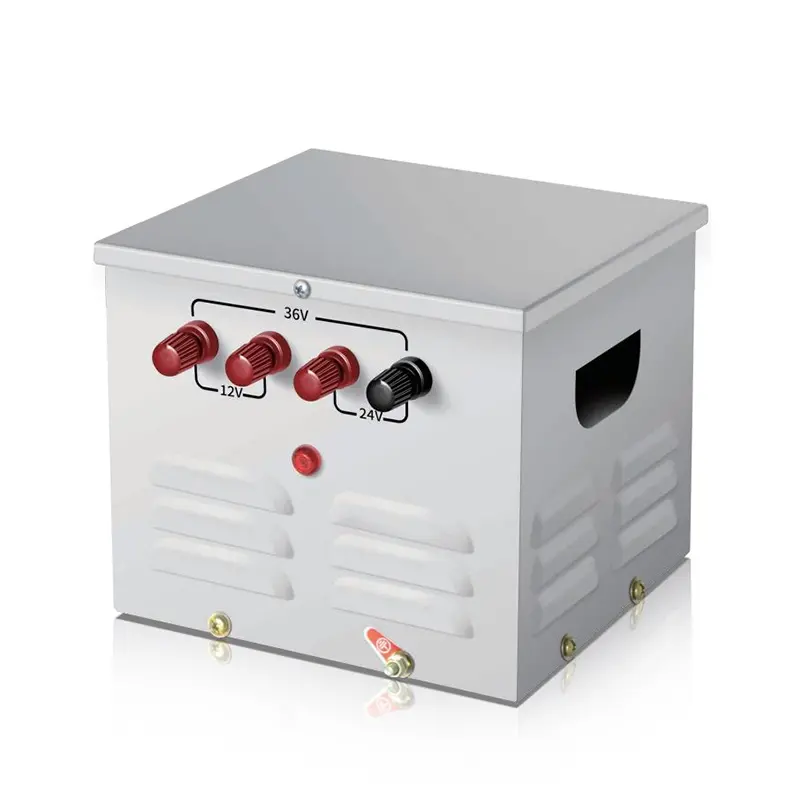
Trasformatore di controllo step-down per illuminazione portatile monofase JMB 25Va~50Kva
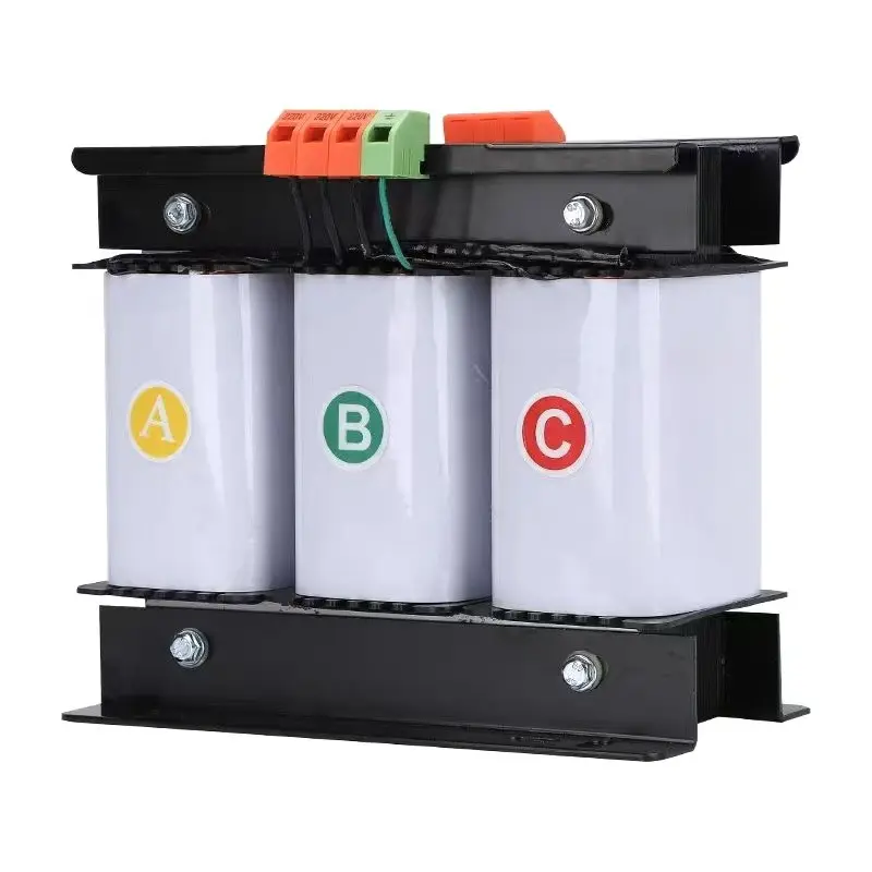
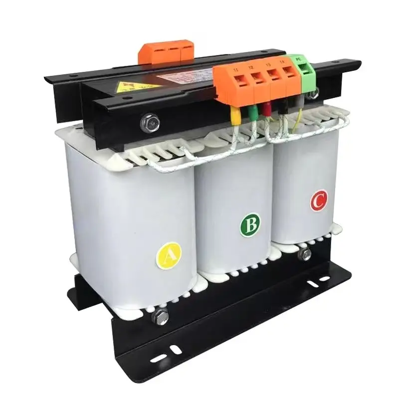
Trasformatore di controllo trifase a secco ad alta efficienza da 500 VA a 1000 KVA 415 V 400 V 380 V