


Проводка изолирующий трансформатор правильное подключение необходимо для обеспечения безопасности, электромагнитной совместимости и надежной работы последующего оборудования. В этом руководстве вы найдете практические шаги, соответствующие стандартам: что нужно проверить перед подключением, как выполнить обычные однофазные и трехфазные соединения, какие тесты и меры предосторожности необходимо выполнить. Всегда поручайте выполнение работ квалифицированному электрику или технику и следуйте местным электротехническим нормам.
Перед началом работы - безопасность и проверка
- Обесточьте, заблокируйте/отметьте и проверьте нулевое напряжение. Никогда не работайте на первичных/вторичных клеммах под напряжением.
- Ознакомьтесь с заводской табличкой и техническим паспортом. Подтвердите первичное/вторичное напряжение, кВА, векторную группу, класс изоляции, номинальный ток и идентификацию клемм.
- Проверьте среду установки. Обеспечьте достаточную вентиляцию, свободное пространство, температуру окружающей среды и высоту над уровнем моря в соответствии с техническим паспортом.
- Соберите инструменты и средства индивидуальной защиты. Калиброванный измерительный прибор, мегомметр, тестер TTR (соотношение оборотов) (если имеется), динамометрический ключ, наконечники с правильным номиналом, изолирующие перчатки, защита глаз.
- Выберите правильные кабели и защитные устройства. Кабельные калибры, выключатели/предохранители и защитные реле, рассчитанные на номинальный ток и пусковые характеристики.
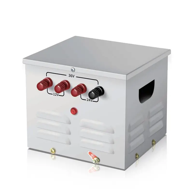
Однофазный разделительный трансформатор - общая проводка (шаг за шагом)
Типичное применение: Изоляция 230 В → 230 В 1:1 или понижающая/повышающая однофазная нагрузка.
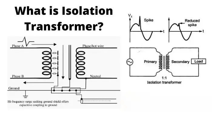
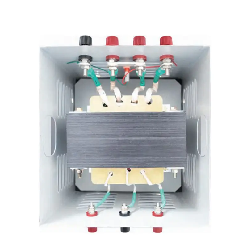
- Идентифицируйте терминалы. Первичные клеммы обычно маркируются H1 / H2 (или L / N). Вторичные обозначаются X1 / X2 (или L' / N'). Клемма заземления/экрана обозначается PE или "Shield".
- Подключите первичное питание. Подключите провод под напряжением (L) к H1 и нейтраль (N) к H2 в соответствии с заводской табличкой. Затяните клеммы с моментом, указанным производителем.
- Подключите защитное заземление. Подключите раму трансформатора и специальный заземляющий зажим к защитному заземлению. При наличии электростатического экрана соедините его дренажную клемму с землей в соответствии с инструкциями производителя.
- Подключите вторичную нагрузку. Подключите нагрузку под напряжением к X1 и нейтраль к X2. Если трансформатор имеет изоляцию 1:1, вы можете оставить вторичную обмотку. незаземленный (плавающей) для максимальной изоляции, или заземлите вторичную нейтраль, если установка требует сплошной нейтрали, - только в соответствии с условиями применения и местными нормами.
- Установите защиту от перегрузки по току. Установите предохранители или выключатели на первичной стороне, рассчитанные на номинальный первичный ток трансформатора; при необходимости предусмотрите вторичную защиту.
- Проверьте проводку. Проверка непрерывности (обесточенный): убедитесь в отсутствии непрерывности первичной и вторичной обмоток. При необходимости проведите тест Megger в соответствии с техническим паспортом. TTR подтверждает соотношение.
Важно: Не создавайте параллельных связей нейтраль/земля на вторичной обмотке без согласования с проектом системы - это может привести к нарушению изоляции и образованию контуров заземления.
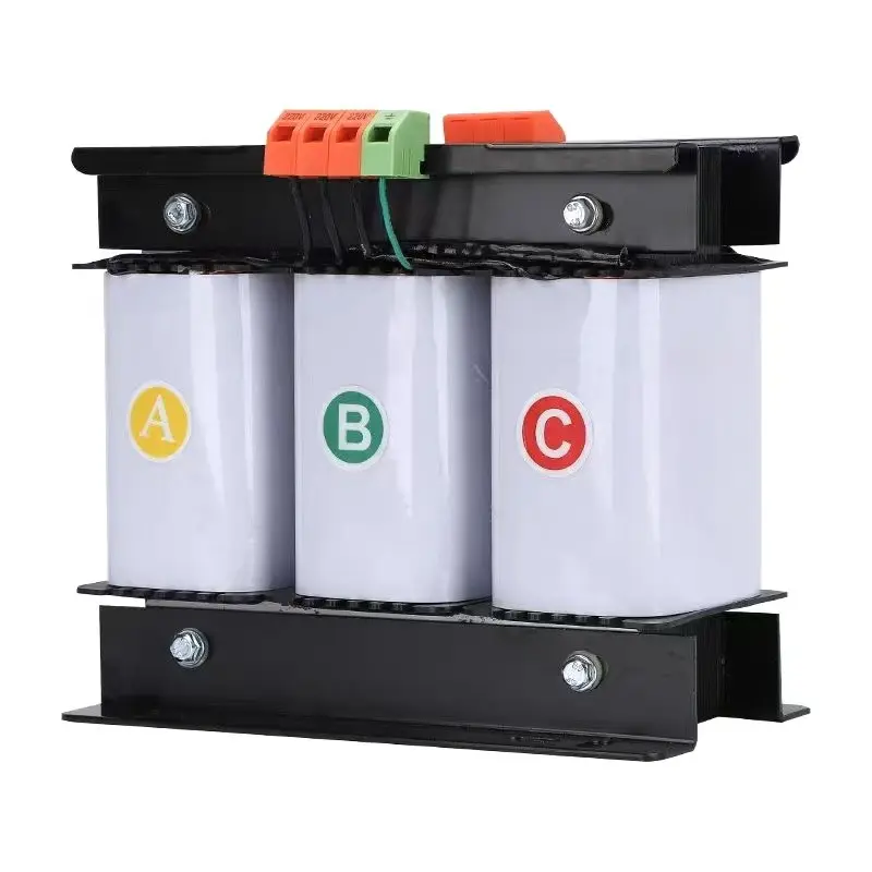
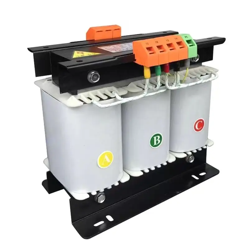
Трехфазный разделительный трансформатор - общие способы подключения и указания по подключению
Трехфазные разделительные трансформаторы часто подключаются в Y (звезда) или Δ (дельта) конфигураций и могут быть подключены как Y-Y, Y-Δ, Δ-Y и т.д. Ваш выбор влияет на фазовый сдвиг (группа векторов) и наличие нейтрали.
- Подтвердите группу векторов (тактовая нотация). На заводской табличке будет указано, например, Dyn11, Yyn0. Это определяет соотношение фаз между первичной и вторичной обмотками и наличие нейтрали. Никогда не смешивайте фазы с несовпадающими группами векторов - это вызывает циркулирующие токи и повреждения.
- Примеры проводки:
- Y-Y с нейтральным (Yyn0): Первичные фазы к H1/H2/H3, первичная нейтраль к Hn. Вторичные фазы к X1/X2/X3, вторичная нейтраль Xn заземлена, если требуется. Хорошо, если нейтраль требуется с обеих сторон и нет сдвига фаз.
- Δ-Y (D-y) step-down с нейтралью на вторичке (Dyn11): Первичная треугольник (без нейтрали), вторичная звезда с нейтралью - обычно используется для создания заземленной нейтрали на вторичной обмотке.
- Заземление и экраны: Если имеется электростатический экран, подключайте экран только к земле в соответствии с инструкциями производителя - это подавляет синфазные помехи, сохраняя гальваническую развязку.
- Последовательное подключение и фазировка: При подключении убедитесь в правильном чередовании фаз. Перед подачей напряжения используйте тестер чередования фаз для подтверждения правильной ориентации.
Испытания и ввод в эксплуатацию (в обесточенном и включенном состоянии)
- Проверка непрерывности (обесточен): между первичными и вторичными контактами должно быть значение "открыто".
- Сопротивление изоляции (мегомметр): Проверьте MΩ между обмотками и на землю в соответствии с техническим описанием.
- Тест на соотношение оборотов (TTR): подтверждение правильного соотношения витков и обнаружение коротких витков.
- Hi-pot (диэлектрический) тест: только квалифицированным персоналом в соответствии со стандартами, если это необходимо.
- Подача напряжения и контроль холостого хода: Подайте напряжение без нагрузки; измерьте напряжение, напряжение нейтрали/заземления и обратите внимание на неожиданный нагрев или звук.
- Испытание нагрузкой: приложите ожидаемую нагрузку и проверьте повышение температуры, регулировку и настройки срабатывания защиты.
Лучшие практики и советы по установке
- Используйте правильный момент затяжки на всех клеммных соединениях, чтобы избежать перегрева.
- Предоставить прозрачные этикетки для первичных/вторичных клемм и точек заземления.
- Сохраняйте первичный и вторичный проводники физически разделены для уменьшения наведенной муфты и облегчения обслуживания.
- Для оборудования, чувствительного к шуму, используйте трансформатор с электростатический экран и тщательно следуйте инструкциям по заземлению.
- Храните электрические схемы производителя и протоколы заводских испытаний вместе с устройством.
Соблюдение и ответственность
Всегда следуйте местным электротехническим нормам (IEC, NEC или региональным эквивалентам), руководству по установке производителя и правилам заземления на объекте. Если трансформатор питает медицинские, лабораторные или критически важные системы, настаивайте на наличии заводских сертификатов испытаний и сертифицированных монтажников.
Вопросы и ответы
Q1 - Нужно ли заземлять вторичную обмотку изолирующего трансформатора?
Зависит от ситуации. Если оставить вторичную нейтраль плавающей, то можно добиться максимальной гальванической развязки, но это может усложнить стратегию защитного заземления. Если нейтраль необходима для защитных устройств или оборудования, заземлите вторичную нейтраль в соответствии с местными правилами и рекомендациями производителя.
Q2 - Как избежать сдвига фаз или контурных токов в трехфазных установках?
Подберите трансформатор векторная группа в точном соответствии с требованиями системы. Никогда не подключайте параллельно трансформаторы с разными векторными группами. Используйте правильные соединения треугольник/звезда и проверяйте чередование фаз перед подачей напряжения.
Q3 - Кто должен выполнять тесты на hi-pot и TTR?
Только обученные, авторизованные технические специалисты должны проводить испытания hi-pot и TTR. Эти испытания требуют надлежащих процедур безопасности и калиброванного оборудования; неправильное тестирование может повредить изоляцию или создать опасность.
Однофазный тороидальный изоляционный трансформатор 220В на 220В с 2 выходными розетками
Однофазный портативный трансформатор управления освещением JMB, понижающий, 25 ВА–50 кВА
Высокоэффективный трёхфазный сухой трансформатор управления 500 ВА–1000 кВА, 415 В / 400 В / 380 В