


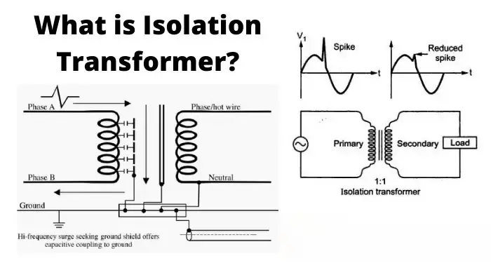
Câblage d'un transformateur d'isolement Un câblage correct est essentiel pour la sécurité, les performances CEM et le fonctionnement fiable de l'équipement en aval. Ce guide vous guide à travers des étapes pratiques et conformes aux normes - ce qu'il faut vérifier avant de câbler, comment effectuer les connexions monophasées et triphasées courantes, et quels sont les tests et les mesures de sécurité à mettre en œuvre. Demandez toujours à un électricien ou à un technicien qualifié d'effectuer le travail et respectez les codes électriques locaux.
Avant de commencer - sécurité et vérification
- Mettre hors tension, verrouiller/étiqueter et vérifier que la tension est nulle. Ne jamais travailler sur des bornes primaires/secondaires sous tension.
- Lire la plaque signalétique et la fiche technique. Confirmer les tensions primaires/secondaires, les kVA, le groupe de vecteurs, la classe d'isolation, le courant nominal et l'identification des bornes.
- Vérifier l'environnement d'installation. Ventilation adéquate, dégagement, température ambiante et limites d'altitude conformément à la fiche technique.
- Rassembler les outils et l'EPI. Compteur étalonné, mégohmmètre, testeur TTR (turns-ratio) (si disponible), clé dynamométrique, cosses de taille correcte, gants isolants, protection des yeux.
- Choisir le câblage et les dispositifs de protection adéquats. Calibre des câbles, disjoncteurs/fusibles et relais de protection dimensionnés pour le courant nominal et les caractéristiques d'appel.
Transformateur d'isolement monophasé - câblage commun (étape par étape)
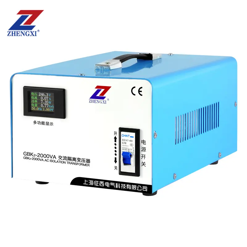
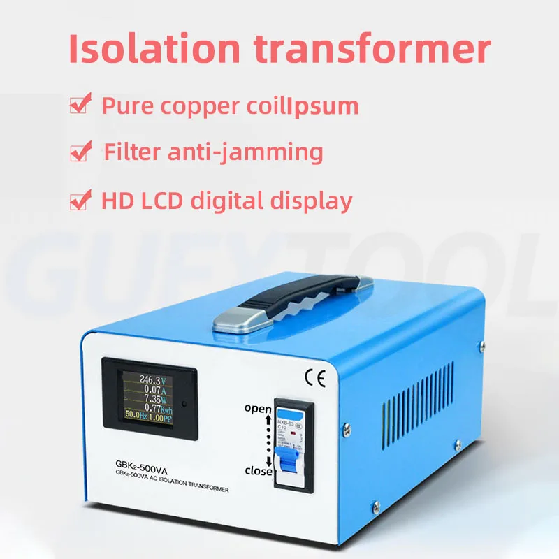
Utilisation typique : Isolation 230 V → 230 V 1:1, ou charges monophasées abaisseuses/élévatrices.
- Identifier les terminaux. Les bornes primaires sont généralement marquées H1 / H2 (ou L / N). Les bornes secondaires sont étiquetées X1 / X2 (ou L' / N'). Borne de terre/blindage étiquetée PE ou "Shield".
- Connecter l'alimentation primaire. Connecter la phase (L) à H1 et le neutre (N) à H2 conformément à la plaque signalétique. Serrer les bornes au couple de serrage du fabricant.
- Connecter la terre de protection. Relier le châssis du transformateur et la borne PE dédiée à la terre de protection du site. Si un écran électrostatique est présent, connectez sa borne de drainage à la terre conformément aux instructions du fabricant.
- Connecter la charge secondaire. Connectez la charge sous tension à X1 et le neutre à X2. Si le transformateur est 1:1 pour l'isolation, vous pouvez choisir de laisser le secondaire sur X1 et le neutre sur X2. sans terre (flottant) pour une isolation maximale, ou mettre à la terre le neutre secondaire si un neutre solide est requis par l'installation - uniquement en fonction de l'application et du code local.
- Installer une protection contre les surintensités. Placer des fusibles ou des disjoncteurs sur le côté primaire, dimensionnés en fonction du courant primaire nominal du transformateur ; envisager une protection secondaire le cas échéant.
- Vérifier le câblage. Contrôle de continuité (hors tension) : confirmer l'absence de continuité primaire↔secondaire. Si nécessaire, effectuer un test Megger conformément à la fiche technique. Le TTR confirme le rapport.
Important : Ne créez pas de liens parallèles entre le neutre et la terre sur le secondaire sans consulter le concepteur du système, car cela peut compromettre l'isolation et créer des boucles de terre.
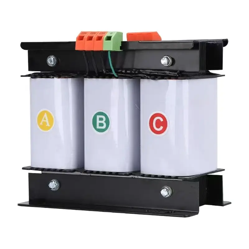
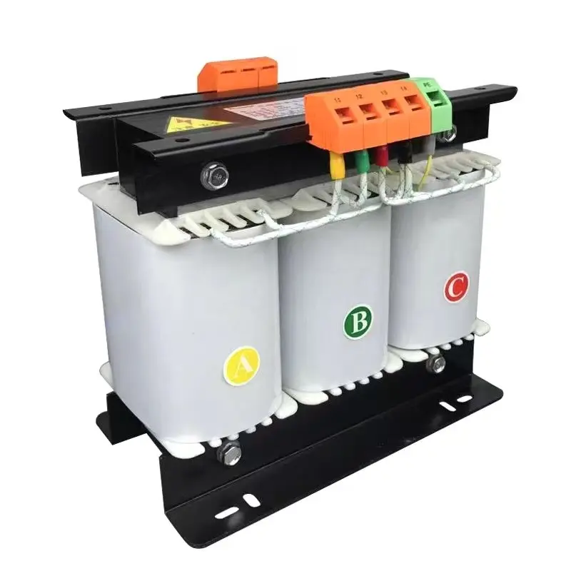
Transformateur d'isolement triphasé - modes de connexion courants et notes sur le câblage
Les transformateurs d'isolement triphasés sont souvent câblés en Y (étoile) ou Δ (delta) et peuvent être connectés en Y-Y, Y-Δ, Δ-Y, etc. Votre choix affecte le déphasage (groupe de vecteurs) et la disponibilité d'un neutre.
- Confirmer le groupe de vecteurs (notation de l'horloge). La plaque signalétique indiquera par exemple Dyn11, Yyn0. Cela définit la relation de phase entre le primaire et le secondaire et la présence ou non d'un neutre. Il ne faut jamais mélanger les phases avec des groupes de vecteurs non appariés, car cela entraîne des courants de circulation et des dommages.
- Exemples de câblage :
- Y-Y avec neutre (Yyn0) : Phases primaires vers H1/H2/H3, neutre primaire vers Hn. Phases secondaires vers X1/X2/X3, neutre secondaire Xn mis à la terre si nécessaire. Bon lorsque le neutre est requis des deux côtés et qu'il n'y a pas de déphasage.
- Δ-Y (D-y) step-down avec neutre sur le secondaire (Dyn11) : Delta primaire (sans neutre), étoile secondaire avec neutre disponible - couramment utilisé pour créer un neutre mis à la terre sur le secondaire.
- Mise à la terre et blindage : S'il existe un blindage électrostatique (écran), connectez-le uniquement à la terre, conformément aux instructions du fabricant - cela supprime les interférences en mode commun tout en maintenant l'isolation galvanique.
- Câblage séquentiel et mise en phase : Lors du raccordement, veillez à ce que l'ordre des phases soit correct. Utiliser un testeur de rotation de phase pour confirmer l'orientation correcte avant de mettre sous tension.
Tests et mise en service (hors tension et sous tension)
- Contrôle de continuité (hors tension) : la lecture primaire-secondaire doit être ouverte.
- Résistance d'isolation (mégohmmètre) : vérifier MΩ entre les enroulements et à la terre selon la fiche technique.
- Test du ratio de rotation (TTR) : confirmer le rapport correct des spires et détecter les spires court-circuitées.
- Essai Hi-pot (diélectrique) : uniquement par du personnel qualifié en respectant les normes si nécessaire.
- Mise sous tension et surveillance à vide : mettre sous tension à vide ; mesurer les tensions, les tensions entre le neutre et la terre, et rechercher des échauffements ou des bruits inattendus.
- Test de charge : appliquer la charge prévue et vérifier l'élévation de température, la régulation et les réglages de déclenchement de la protection.
Meilleures pratiques et conseils d'installation
- Utilisation couple correct sur toutes les connexions terminales afin d'éviter toute surchauffe.
- Fournir étiquettes transparentes pour les bornes primaires/secondaires et les points de mise à la terre.
- Garder conducteurs primaires et secondaires physiquement séparés pour réduire le couplage induit et faciliter l'entretien.
- Pour les équipements sensibles au bruit, utilisez un transformateur avec un bouclier électrostatique et suivre attentivement les instructions de mise à la terre.
- Conservez les schémas de câblage du fabricant et les rapports d'essai de l'usine avec l'appareil.
Conformité et responsabilité
Respectez toujours les codes électriques locaux (IEC, NEC ou équivalents régionaux), le manuel d'installation du fabricant et les règles de mise à la terre du site. Si le transformateur alimente des systèmes médicaux, des laboratoires ou des systèmes de sécurité critiques, exigez des certificats d'essai d'usine et des installateurs certifiés.
FAQ
Q1 - Dois-je mettre à la terre le secondaire d'un transformateur d'isolement ?
Cela dépend. Laisser le secondaire flottant maximise l'isolation galvanique mais peut compliquer les stratégies de mise à la terre. Si un neutre est nécessaire pour les dispositifs de protection ou l'équipement, mettez le neutre secondaire à la terre conformément au code local et aux instructions du fabricant.
Q2 - Comment éviter les déphasages ou les courants circulants dans les installations triphasées ?
Faire correspondre les groupe de vecteurs exactement aux exigences du système. Ne jamais mettre en parallèle des transformateurs avec des groupes de vecteurs différents. Utiliser les connexions delta/étoile correctes et confirmer la rotation des phases avant la mise sous tension.
Q3 - Qui doit effectuer les tests hi-pot et TTR ?
Seuls des techniciens formés et agréés peuvent effectuer des tests sur le point haut et le TTR. Ces tests nécessitent des procédures de sécurité appropriées et un équipement calibré ; un test incorrect peut endommager l'isolation ou créer des risques.
Transformateur d'isolement toroïdal monophasé 220v vers 220v avec 2 prises de sortie
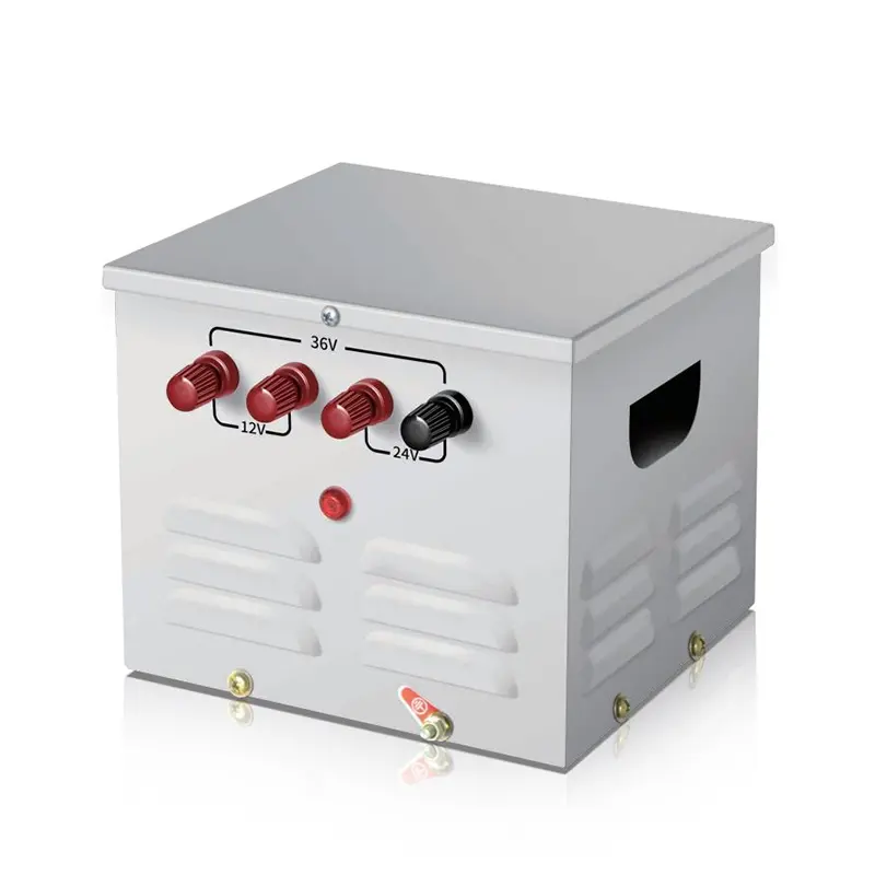
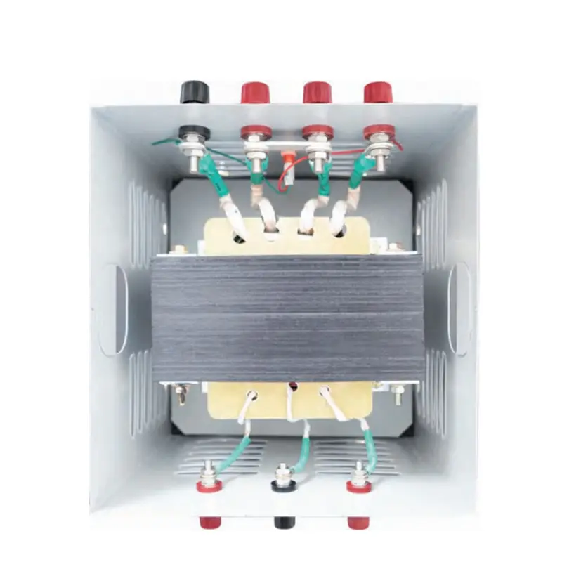
Transformateur abaisseur de tension d'éclairage portable monophasé JMB 25 V à 50 kVA
Transformateur de commande triphasé à sec haute efficacité 500 VA-1 000 kVA 415 V 400 V 380 V